
Imitate popular large metal marquee letters
with
this miniature version.
Bulbs of 20 light mini set from Darice
(wreath applications
are suggested by mfgr.)
are pushed through holes and held in place
by built-up
ring "collars" (shown in model as white
to amplify mini lights;
can
be made to match letter body if preferred).
Letter edges are built up with
slightly deeper "flanges",
cut individually to make adjustments easier
due to card stock paper thickness.
Mini light battery canister is
camouflage-encased
in a sized-to-fit box with lid and cutouts
with on/off
switch accessible.
Built up foundation shape is included
to attach letters and
battery box.
Letters measure approx. 6" tall x 1.5" deep.
Overall
display (not including foundation extension
for battery box) is approx.
10.75" wide.
LIGHTS SET INFORMATION :
The mini lights set that is used for this project
is by Darice: Deco Lights teeny bulbs 20 lights, which
is battery powered (hence the artwork that is
shown as part of the battery housing though the
2 "C" batteries are NOT included).
The product number ID is BT20-1 white wire/clear teeny bulb.
Scan code numbers: 652695539725
One package costs under $5.
I purchased mine from JoAnn Fabrics walk-in store.
They are also available on-line from many locations.
 With batteries in place, a metal level is pivoted
to make the connection that sends power
to the string of lights.
When lit, the lights put of virtually NO heat.
Packaging text includes: "Great for
centerpieces. Glue on Wreaths."
However, it is not recommended to leave the
lights on for extended periods of time,
nor to leave them unattended.
Suggested use of this product for this project
on this blog does NOT constitute any responsibility
on the part of Jodi G. Warner or SnapDragon Snippets
for any problems/damage caused as a result
of the light malfunction or combustion.
 ASSEMBLY:
1. Identify and cut the shapes for the letters
(cut one B, two O):
A main "B" hull shape B extra side boxing
C interior opening boxing upper & lower
D inner vert support struts (2)
E outer & inner edge flanges (see more below)
F collar rings (8 per opening x 20 for BOO)
G main "O" hull shape H vert struts (2)
I interior opening boxing strip
J outer edge flanges K inner edge flanges


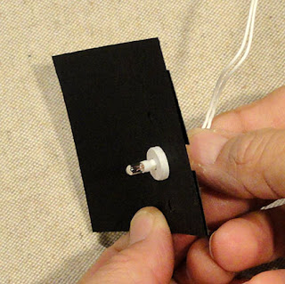
 This is an out-of-focus (apologies) shot
showing the thickness of the 8 layer built-up collar.


 5. Form the interior boxing shape into a ring
to bring the side straight edge to overlap on
the inside of the side tab, adjust and glue in place.
Repeat for the other boxing shape.
 6. With the "B" housing laying face down on work surface,
identify the upper opening boxing assembly,
and note that the narrow panel indicated here . . .
 . . . will line up with the narrow lower corner panel
indicated here.

 . . . quickly turn assembly to front to
make adjustments as needed.
Work for the best, most accurate alignment
possible.

 During this process, prepare the double panel
boxing addition that creates the boxing at B shape's
right edge indent near center by bending center perf
inward and tabs back.
Position and attach this addition at corresponding
side tabs, and attaching top tabs under the "B" edges.


 . . . the back strut in the same manner

 11. Identify the narrow flanges for the "B"
interior openings by noting that for each opening
there will be one narrow and one wide.

 . . . then the lower wider flange . . .


 . . . then adding the remaining flanges all around.


 16. Form the strip into a ring to overlap straight
side edge over side tab.
(Tab should be behind strip edge, showing
from the back side of the assembly.)


 20. With all three letters completed,
lay them side by side on work surface,
align bottom edges to be even as they will
be when the assembly "stands".
Apply "quick grab" adhesive to the faces that will touch
(such as the hot glue being added here,)
then carefully attach the letters into one unit.


 . . . direct the wires across the front and along
the left side (as viewed from the front) . . .


 Insert the first light beyond the long attachment
wire section into the front "B" bottom hole . . .
 (another view of the first light insertion)
. . . then continue to string the lights up and around
the "B", using the notches in the support struts
to help the wires string as required.
Then string the wire over the attached "B" and "O"
walls to insert in bottom "O" hole, up and around,
then across to the "O", etc.
 28. Gather the excess wiring behind the battery
and band with tape if desired.
Tuck into the bottom of the B.
 Also tuck the wires into the letter backs
as thoroughly as possible.
NOTE it may be advisable to use small strips
of electrical (black) tape to manage the wire.


The mini lights set that is used for this project
is by Darice: Deco Lights teeny bulbs 20 lights, which
is battery powered (hence the artwork that is
shown as part of the battery housing though the
2 "C" batteries are NOT included).
The product number ID is BT20-1 white wire/clear teeny bulb.
Scan code numbers: 652695539725
One package costs under $5.
I purchased mine from JoAnn Fabrics walk-in store.
They are also available on-line from many locations.

to make the connection that sends power
to the string of lights.
When lit, the lights put of virtually NO heat.
Packaging text includes: "Great for
centerpieces. Glue on Wreaths."
However, it is not recommended to leave the
lights on for extended periods of time,
nor to leave them unattended.
Suggested use of this product for this project
on this blog does NOT constitute any responsibility
on the part of Jodi G. Warner or SnapDragon Snippets
for any problems/damage caused as a result
of the light malfunction or combustion.

1. Identify and cut the shapes for the letters
(cut one B, two O):
A main "B" hull shape B extra side boxing
C interior opening boxing upper & lower
D inner vert support struts (2)
E outer & inner edge flanges (see more below)
F collar rings (8 per opening x 20 for BOO)
G main "O" hull shape H vert struts (2)
I interior opening boxing strip
J outer edge flanges K inner edge flanges

L battery box housing
M base platform build up (4)

Th design of these letters includes separate
edge flanges which have a fold-down top rim
that extends approx. 1/4" beyond the platform
where the lights and collars extend..
Each flange is attached to a specific "face"
around the outside and also inner openings.
Being separate, they can be trimmed down
if necessary, which may be necessary due to
varying thickness of card stock used.
Our usual "tolerances" for textured card stock
was used in the sizing. I used 110#
which is slightly thicker, and some trimming
was necessary.
Below are the "B" flange shapes laid out
in their approximate positions around the B
1-6 are for the outer edges. 7 group is for
upper interior opening. 8 group is for
lower interior opening.
Groups 7 & 8 include the same shapes,
but their positioning is horizontal mirrored.

2. Prepare the mini light collars build up,
which help hold the lights in position.
Position and glue together a stack of 8 rings
for each of the 20 lights in the set.
This can go quickly, but TAKE CARE that
the edges line up as precisely as possible.
My choice for the sample project was to make these
white and place them on the outside face of
the letters.
Other good choices: i) make them match housing;
ii) place them on the underside of the housing
so that they don't show.

showing the thickness of the 8 layer built-up collar.

3. Position and attach one collar at each light hole
opening on the "B" main shape. Make sure they
attach firmly. It may be helpful to use a flat
weight during the glue-drying process.

4. Prepare the interior opening boxing shape
by bending forward on all the vertical perforation lines,
and bending top edge tabs back.
REMEMBER that the upper and lower openings
will required their specific boxing, so make sure
that both the shapes from the cut file are cut.
The lower boxing includes an "X" cut in the side tab.

to bring the side straight edge to overlap on
the inside of the side tab, adjust and glue in place.
Repeat for the other boxing shape.

identify the upper opening boxing assembly,
and note that the narrow panel indicated here . . .

indicated here.

7. Apply glue to the face of upper edge tabs
of interior boxing, then position over the
backside of the opening, taking care to align
the edges of the opening with the tab perforation
lines. Complete initial alignment, then . . .

make adjustments as needed.
Work for the best, most accurate alignment
possible.

8. Form the B hull into its "box" shape by bending
the edges into position to complete the seams.
Straight edges should overlap adjacent tabs
to perforation lines.

boxing addition that creates the boxing at B shape's
right edge indent near center by bending center perf
inward and tabs back.
Position and attach this addition at corresponding
side tabs, and attaching top tabs under the "B" edges.

9. Prepare the "B" vertical support strut strips
by bending end tabs back in opposite directions
as shown.

Position and attach on the inside of "B" assembly
flush next to the interior opening boxing back side,
attaching end tabs to top and bottom
in the same step. NOTE that notches face out.
Shown here is the back strut.
Also position and attach . . .


10. Prepare each edge flange by bending back and
creasing the top rim perforation. Glue rim tab in place.

interior openings by noting that for each opening
there will be one narrow and one wide.

12. Apply adhesive to the back side of flange
below rim tab, then position over the corresponding
face, bottom edges even, top edge of hull snugly
abutted to the rim tab lower edge.
Begin with the narrow flanges, here the narrow upper . . .


. . . then continue with the remaining flanges,
first testing it in position to note any trimming
for appropriate length that may be necessary,
then applying adhesive and attaching.

13. Repeat the process for the outer edge flanges,
including the "double" indent flange shown here . . .


14. The process to assembly the "O" form is similar.
First, prepare the main hull shape by bending
back on ALL perforation lines . . .

. . . positioning and attaching collar "stacks"
at each light opening.

15. Prepare the interior opening boxing strip
by bending forward on all vertical perf lines,
bending back on top tabs.
NOTE that the narrow interior panels for the "O"
are all the same width.

side edge over side tab.
(Tab should be behind strip edge, showing
from the back side of the assembly.)

17. Position and attach the interior boxing
to the underside of the "O" hull in the same
manner as for the "B" (step 7).

18. Bend edges in place to complete the "O"
side seams in same manner as for "B".

19. Prepare, then position and attach the
interior flanges, beginning with the narrowest . . .

. . . then measuring, trimming if necessary,
and adding the other flanges around.

Also position and attach the outer flanges.

lay them side by side on work surface,
align bottom edges to be even as they will
be when the assembly "stands".
Apply "quick grab" adhesive to the faces that will touch
(such as the hot glue being added here,)
then carefully attach the letters into one unit.

21. The letters can be used independent of
the base platform, if desired. With the platform,
the battery will be more easily dealt with.
Without the platform, the battery could be "hidden"
behind nearby objects in your display.
* * *
Prepare the platform by layering and attaching the
multiple cut shapes (sample uses 4 shapes of 110#;
cut and build up your platform with as many layers
as is necessary for sturdy base. Take care that
edges align as precisely as possible.

22. NOTE that the battery box assembly
and battery will be demonstrated in its
"unattached" form first. Once its assembly
is understood, it will be necessary to
to remove the battery housing itself in order
to attach the box to the platform (step 26).
* * *
Prepare the battery box by bending back on
all perforation box lines and tabs except
the insertion tabs of roof flaps should be left unbent.

23. NOTE that the right back side seam tab
will be left unattached to allow for the battery
wire to slide into place.

Fold the sides of the box upward to bring together
side straight edges to overlap adjacent side tabs,
and complete the other three seams . . .

. . . leaving the back right seam unattached.

24. Place the battery container (with batteries inside)
into the prepared box with the activation switch
toward the top as shown . . .

the left side (as viewed from the front) . . .

. . . and out the back opening where the side seam
is unattached. If desired, close the seam with
temporary adhesive such as adhesive roll-on dots, etc.

25. Close the top of the box by bending into
position, inserting the side and back tabs into
corresponding slots.

26. Position and attach box bottom
on the platform extension,
with the lever opening toward the very back,
and the three punch holes of each aligned.

27. This cut-away will show how the mini lights
are inserted and pushed fully
into their openings with collar.

wire section into the front "B" bottom hole . . .

. . . then continue to string the lights up and around
the "B", using the notches in the support struts
to help the wires string as required.
Then string the wire over the attached "B" and "O"
walls to insert in bottom "O" hole, up and around,
then across to the "O", etc.

and band with tape if desired.
Tuck into the bottom of the B.

as thoroughly as possible.
NOTE it may be advisable to use small strips
of electrical (black) tape to manage the wire.

Here is the lighted assembled display to this point.
29. Position (centered) the letters on the front of
the platform panel, and attach with
quick grab glue (such as hot glue).

Here is the completed display.

No comments:
Post a Comment