
Re-imagine the mythic imp’s love-spreading weapon
as a steam punk high-tech dart shooter.
Details of this
Valentine’s Day display piece include:
dimensional hull, barrel (strengthened
with a .75” diam. wooden dowel),
cone shaped muzzle end, radiating sphere
collars,
undercarriage trigger assembly, top mount dart holder tubes,
back canister,
pair of four-finned arrow-tipped darts
(strengthened with standard bamboo
skewer
slightly narrower than .125” diam. dowel) in holders.

Optional simple
stand will assist display, if desired.
Add metal findings such as gear wheels,
studs, keys and more.
This sophisticated model is geared to paper crafters
with
construction experience.

at front muzzle bell (2.25” at main hull) when fully assembled.
GEN. ASSEMBLY: 1. Identify and cut the shapes:
A main hull tube B hull back end double wall
C under-hull trigger housing "box"
D trigger stack (quantity determined by slot test V; see Step 2):
1 top layer, *5 interior trigger layers, 1 bottom layer
E muzzle bell end F bell edge trim shapes (6)
G muzzle cone wedges (6) H muzzle interior wall
I muzzle end panel with spiral accent
J dart holder tube (2) K edge trim for J (2 x 6)
L sighting nub: 2 outer with tab, *5 interior
M rear array with trim circles (2); not shown: underside support
N & O grip inner support posts with inner struts (2 sets)
P grip main shape Q left, right grip accent overlays & accents
R grip lower accent strips: left, right, center front
S barrel tube (dowel wrap)
T radiating ring assemblies for 3 sizes: 5 each
U rear cannister tube with interior support struts
*V slot test: strips and slot panel to determine how many
layers of selected stock can snugly be inserted through slot
to determine quantity of layers for D & L
W dart arrow shapes (2 sets): shaft, fins, arrow tips, overlays

Optional stand shapes (left to right):
support with bottom plus top tab
support with bottom tag
support accent overlays (2)
base stand (4 to stack for thickness, weight)
base stand top accent layer with support slots
(Stand assembly begins at Step 69.)

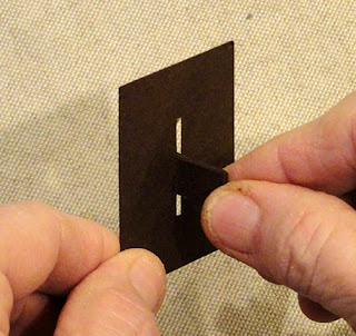
2. Use the slot test shapes cut from selected stock for
trigger layers and/or sight nub layers to determine
how many of those shapes to cut.
Stack 7 strips on top of each other, then . . .

. . . see if the stack will fit through the panel's slot.
NOTE that when these are glued together for the actual
assemblies, they may be somewhat more snug.
The target is a snug fit that can be inserted into slot.
If the 7 are thin, add the 8th strip and check.
Use the determined quantity to cut the trigger and sight nub.
PRE-ASSEMBLY OF COMPONENTS
4. Layer and glue together the 5-6 interior trigger shapes
that will show thru as the trigger lever, taking care that
ALL cut edges align as precisely as possible.

Add the contrast front and back layers (without lever)
and attach in place, keeping tabs unattached.

For all shapes that are layered and glued together
using liquid adhesive, it is strongly recommended to
place on a flat surface, then press with a flat heavy object
such as a thick book or other equivalent, possibly with
additional heavy weight placed on top. Leave the weights
in place until the stack is thoroughly dried, which may
require hours or over night, to help prevent or minimize
warping or curling of the shape.

5. Stack and glue together each of the three sizes of
radiating barrel rings, taking care that the center hexagon
edges are lined up as precisely as possible so that
the rings will fit over the barrel tube with dowel during
final assembly. Press under weights while drying.

6. NOTE: the sight shape was changed slightly in final cut file.
Bend the bottom tabs of sight numb outward.
Layer and glue together the 5-6 interior (no tab) shapes
then layer the matching portion of the outer (tabbed)
shapes on top and bottom of the stack, with curved nub
edges of all layers aligned. Press under weight til dry.

7. Prepare the grip accent overlay assemblies by
positioning and attaching the three "ridge stripe" shapes
and bottom strip accent onto the narrower overlay.

Then position and attach the accent assembly onto
the back portion of the grip side overlay.
(Complete a left and a right assembly.)

8. Prepare the main grip shape by bending back on
the two vertical perforation lines; bend forward on
the top center tab and side top edge shaped flanges.
Position and attach the crescent trim accent on
center bottom, between perf lines.

9. Position and attach the spiral accent shape onto
the muzzle end accent panel. NOTE: it is best to try
to position the spiral so that the start and end "tails"
are near the horizontal "equator" when the 'X' arrow fin
slots are oriented as shown.

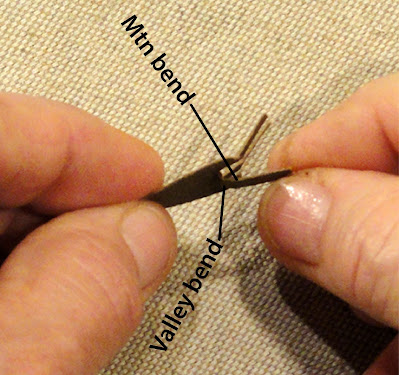
10. Prepare the tail array by bending the "arm" structures
as shown: bottom tabs forward, center perf line back,
top perf line near hole forward.

11. Position the arms back to back, align and glue together
the hole tabs ONLY together.

Also prepare the under support as shown. Then . . .

. . . apply glue to the support backside, fit it under
the "arch" of main arms assembly, with center perf
angle fitting snuggly behind the tab extension joint,
other perf line angles, edges aligned, and attach.

Position and attach the accent rings on front and back.

12. Prepare the main hull back panel insert by bending
outer tabs forward.
Insert arm array structure end tabs into slot pairs
(there is NO top or bottom to panel). On backside,
bend tabs outward and glue in place.

13. Prepare the rear cannister tube by bending back
on all perforations for walls, end caps, tabs.

14. Form the shape into a tube to overlap the straight
side edge across the opposite tab flange and glue in place.

NOTE that the symmetry of the tube shape will allow
it to be pressed flat to apply fingertip pressure along seam.

15. At one end, bend the top wedge tabs inward,
apply glue to surface of each, then bend end cap hex
into position, adjusting so that cap edges align with
tab perf lines, then attaching in place.

16. Prepare the interior support strut strips by
interlocking the slots as shown, so that strips form 'X'.

Bend end tabs outward, then insert the struts into tube
so that X arm ends fit into pairs of angles across opening
as shown.

Repeat Step 15 to close second tube end.

17. Prepare dart holder tubes by bending top "cap" edge
tabs forward, all other perf lines back.

18. Form the shape into a tube to overlap and join
the side seam.

Bend bottom wedge tabs inward, apply glue,
then bend bottom cap in place, adjust and attach.

NOTE that it will be helpful to reach inside this short tube
to apply fingertip pressure around to join tabs in place.

19. Apply glue to the inside rim of tube (match depth of
top cap edge tabs), then bend the cap into position so that
it slides inside the tube.

Push into place until tab and tube rim edges line up.

20. Position and attach each trim section around top rim.

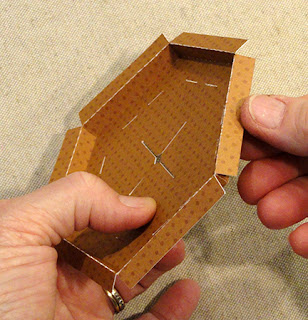
21. Prepare the muzzle bell end shape by bending
at inward wall perforations as "valley" folds,
outer wall perfs as "mountain" folds.
Also bend the tiny connector tabs forward.

22. Bend inward walls upward at 90 degree angle,
position tab behind adjacent wall, and glue in place.
Repeat around the panel.

23. Bend outer wall "flanges" down into position
and glue each to the inner wall backside.
24. Bend the rim strip accent strips as "mountain" folds,
then position each, centered and folds snugly together,
at a wall "facet", and attach in place.

25. Prepare each cone wedge shape by bending
as shown: top tabs forward, second perf back,
next perf and bottom "tab" perf forward. Also bend
side edge tabs back.

26. Position two wedge shapes side by side, overlapping
the straight side edges of left shape as shown, with
the longest segments aligning, and glue that portion of seam.

Move upward to next segment, adjust the bends so
that the edges align, and glue that portion of seam.

Repeat for top segment and . . .

. . . bottom segment in sequence.

27. Position the next cone wedge shape and attach
the side segments in order as described in Step 26.
Then continue to add the remaining wedges one by one
until they are all attached, and the final seaming sequence
completes the cone.

28. Prepare the interior panel by bending outer edge tabs
upward. Apply glue to outer surface of each tab, then
drop into position inside the cone, rotating so that
panel perf edges fit into the narrowing space at second
perf level. Apply pressure to attach in place.
(This panel will be the "stop" for the barrel end.)

29. Prepare the barrel tube shape by bending back
on each long perforation line and side flange,
also bend top "petal" tabs as "valley" folds.

30. Form the shape into a tube to bring straight side
edge around to overlap long flange tab, and glue seam.

NOTE it may be helpful (providing press-against surface
and also achieving correct fit) to use the 3/4" diam. dowel
that will fill the tube and provide support and weight as
a form to assist with the seam gluing.

31. Measure and cut the dowel insert to be the length
of the barrel tube - from cut end to tabs perf line -
plus 1/4" extra to extend beyond hull cannister to
back wall insert.

Insert the dowel into the tube, slide into place with
front/straight cut ends flush, and apply a little glue
inside tube at each end to hold in place.

MAIN ASSEMBLY SEQUENCE
32. Prepare the main hull cannister by bending back
as "mountain" folds all perforations, except at
end cap tabs, which are bent forward as "valley".

Become familiar with the various slots and
openings. At the back end at top, this perpendicular slot
is for the sight nub. The two slots above it are
positioning slots (and dart tip receptacles).

At bottom, the center wide slots will receive
the trigger stack, the narrow side slots will
allow trigger mech housing to attach.

33. Push the sight nub through the slot from
the underside of the hull shape, and . . .

. . . push through until tab perforations are even with
the slot edge.

On the underside of hull, bend tabs back and glue
to attach to the hull.

34. Prepare the trigger mech housing shape by
bending back on all perforation lines, except
bend top edge tabs forward.

Also, use a blade-like tool such as the spatula tool used
here to bend the four narrow tabs in the slot back to
open the path for the trigger assembly stack.

35. Bend the sides back, side tabs inward,
ends inward to form the "box", and glue seams.

36. Identify the BACK of the mech housing as
the slanted edges - which will correspond to the slant
of the grip handle assembly - then orient the right angle
front edge where it will be closer to front edge,
then insert tabs into slots . . .

. . . then on underside bend tabs back/outward,
apply adhesive to appropriate surface, and attach
to underside of main hull.

37. In preparation for inserting and attaching the trigger
stack, carefully apply glue to the narrow slot tabs.

Also apply glue to the "flat" surface between tabs
(and to the tabs that will be bent downward), then . . .

. . . insert trigger stack (with ring toward hull's front)
into the housing slot, and . . .

. . . fish around until tabs also fit into hull wide slots.
Push trigger in fully so that the flat area between tabs
seats fully against hull wall. Bend trigger tabs outward
and attach to hull underside using as much pressure
as is possible, given the assembly's configuration.

38. Form the hull into a tube to overlap straight edge
across side flange, adjust and glue seam.

39. At the ends, apply glue to the end cap panel's
edge tabs, including the attached tab, then bend cap panel
back into place so that the cap is inside the tube.
Adjust depth of panels/tab edges to be even with
hull edges, then apply pressure until all tabs are secure.
Repeat for both ends - back end is deeper.

40. Insert the front end of barrel post into the back end
of the hull assembly, and push through to exit
through the front end cap's hex opening.
Continue pushing through until back end petal tabs
stop with perf line even at end cap opening edge.

41. Bend petal tabs outward, apply glue to underside . . .

. . . then press to attach to end cap surface all around.

42. Thread the radiating rings onto the front post end,
smallest first, then middle-sized, then largest.
Move rings back toward hull to get them out of the way.

43. Apply glue to the dowel end of post, then . . .

. . . apply glue to the underside of curved tabs . . .

. . . slide the cone narrow end onto post end.

Push the cone fully into place until the post end rests
fully behind interior panel, and apply pressure to
fully attach in place. Also . . .

. . . apply pressure all around the narrow end to
attach cone tabs to post wrap.

44. Move the radiating rings into their final positions,
more or less centered between cone tabs and hull rim,
with even margins between. Move slightly to carefully
apply a line of glue where the ring opening will rest,
then return rings into position. Hold in place until attached.

45. Position bell end assembly with underside facing
cone end tabs (pay attention to orientation of
the 'X' slots so they will be north/south in relation to hull,
then adjust to insert each pair of tabs
into corresponding slots.

Work tabs fully through, then bend outward and
glue in place.

46. Apply glue to the underside of spiral panel assembly
(suggested adhesive is quick-grab glue such as Fabri-Tack)
then position so that 'X' slots of panel align with
bell end panel, and attach in place.

47. At the hull back end, apply glue to dowel end . . .

. . . position the back array/end cap panel - with
array orientation aligned with main hull so that
the rear array sides will be parallel to hull's side edges -
adjust and slide into the back of hull . . .

. . . and push inward until tab edges and rim edges
are even. Apply finger tips pressure to attach each
tab and edge together, all around.

Also push with fingertip between side walls of array
to attach dowel end to backside of panel.

47. Prepare grip post supports by bending back on all
long perforation lines, and forward at tab perf cuts.

Form the post shape into a square tube to overlap
straight edge across tab and join side seam.
Complete two posts this way.
47. Prepare support struts by interlocking slots
(similar to rear cannister struts), then . . .

. . . insert struts into tube with arms ends aligning
at corner bends.

Push down inside tube to be centered inside.

48. Push end tabs of first post through top square
opening until tab perfs rest at opening edge,
then bend tabs . . .

. . . outward and glue in place.

49. Adjust grip so that other end of post can be
inserted through opening, then . . .

. . . repeat the bending outward and attaching of tabs.
50. Repeat for the second post, to insert and attach
in place at lower openings.

51. Prepare the grip tail stabilizer by bending back
on side perforations to create side flanges with
shaped edges. Position stabilizer between grip walls
at back, adjust so that shaped edges of both shapes
align, and glue flanges in place to backside of grip.

52. Position and attach appropriate grip overlay accent
assemblies onto each side of grip assembly.

NOTE it will be helpful to reach fingertips inside of
grip around posts to apply pressure to layers to
achieve a thorough attachment.

53. Bend the center grip tab inward, then apply glue
to the upper surface, and . . .

. . . to backside of shaped upper tabs of grip.
Not shown: also apply glue to back slanted panel
of the trigger mech housing. Then . . .

. . . position at underside at back of cannister hull.
Grip flanges should hug the hull walls on each side
of the bottom wall. Check to make sure . . .

. . . the inward angles of grip side panels align with hull's
octagonal bends at bottom panel (this may require
a moderate amount of force to keep it in place
until glue grabs) and also press so grip attaches
to trigger mech slant wall.

At the same time, work to make sure that the shaped
grip tabs stay aligned where they should and don't slip
away from angle toward back of hull.
54. Locate the slots on one face of the rear cannister, then . . .

. . . apply glue to the tiny nib tab and along
shaped edges at top of grip side walls . . .

. . . and also along the lower back edge of hull.

Position the rear cannister so that the two slots
accept the nib tabs of grip edges, and apply pressure . . .

. . . so that the cannister seats into the shaped edges.
Hold in place until firmly attached.

55. Position and attach the two dart holder tube assemblies
on the main hull's top panel, so that the slot of holder
aligns as precisely as possible with the slot on hull wall.

NOTE that it may be helpful to insert a blade tool
such as a long nail file through the tube then into hull
slot to help with alignment.

DART ASSEMBLY
(Prepare 2 dart arrows)
56. Prepare the dart shaft shape by carefully bending
back at each long perforation line. Also bend top "cap"
attached square back.

57. Form the shape into a tube to overlap straight
long edge across opposite flange tab to join side seam.

NOTE: It may be helpful to insert the dowel/bamboo
skewer that will eventually be inserted to reinforce
the shaft ,

58. Push the skewer into tube and align top end at
"cap" perforation, then . . .

. . . mark end of tube onto stick, then remove
and cut to marked length (sand ends flat ).
Reinsert and glue in place.
Glue top "cap" tab to top end of stick.

59. Prepare the dart fin shapes by bending each "half"
forward along perforation line, resulting in
a narrow section between.
60. Position and attach the backside of first fin
along one shaft face . . .

. . . leaving approx. 1/4" of shaft
end exposed above.

61. Position the second fin so that two halves will
match up back-to-back, and join the aligned halves
while also attaching the center section to shaft.
NOTE: if the first fin selected includes the cord attachment
hole, select and match the second fin that will have
the reverse-matched fin half.
62. Continue the process to position, align and attach
the remaining 2 fin sections.

63. Prepare the arrow tip shapes by bending the center
extension at the two tiny perf cuts so that . . .

. . . it makes a little shelf against which the shaft end will sit.
64. Apply glue to the center extension and both side extensions.
Tuck the bottom shaft end into the "shelf" so that center
extension tucks around it, and the extension rides upward
directly along the shaft wall.

Also push each side extension upward to attach
to the side panels. Apply pressure all around shaft
until extensions are firmly attached.

65. Repeat for the second arrow tip, also aligning
and attaching arrow tips back to back.

66. Position and attach a tip accent shape on each side
of the arrow tip assembly.

67. Reinforce and camouflage the attachment tabs
by "lashing" across the area with a thin cord such as
the twine/perle cotton no. 5 shown on the sample project.
A) cut a 12" length; B) fold a loop approx. 2" from end;
C) place loop approx. 1/4" above top of extension where
it will remain to help tuck ends under lashing;

D) hold loop in place while beginning to wrap the loose
end around the arrow "collar";

E) wrap approx. 8-9 circuits, or until the collar is
fully hidden under the lashing.

F) insert the wrapping tail through the loop still visible
at top of lashing . . .

. . . and pull up excess.

G) carefully pull the bottom tail to ease the top
tail down behind the lashing rows.

H) clip both tails close to top or bottom wrap row.

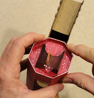
68. To "store" darts, insert the tip into the holder top panel
so that arrow tip wings will slide into slots.
Continue to push down so that arrow tip settles into
the slot on top of hull.

Also NOTE that the dart fin end can fit into the 'X' slots
on the bell end panel as shown.

Here is the basic assembled dart gun.

Add optional findings and embellishments, including:
cord length (coiled) to attach dart fin to trigger front ring;
studs to grip shaped flange, cone narrow end,
at main hull punch holes at front end;
metal gear(s) with metal key, etc.
(NOTE that thickened large gear shape comes from
a separate Hearthsewn design "Cupid Wing Pull Tab Card"
no. 176575 in the Silhouette America online store.)

OPTIONAL STAND ASSEMBLY
69. Layer and attach the base shapes to each other,
taking care to align outer cut edges precisely.
Press under a heavy flat weight until fully dried.

70. Prepare the two "leg" extensions by bending
the bottom flanges forward. Also bend the top extension
on tallest back on both perf lines.

71. Join the short to the long leg panel at top tab,
leaving narrow top section between.
This is the surface that will touch the underside
of dart gun when in place.

72. Position and attach accent panels down center
of each leg, with heart cut outs aligned.
Press under flat weight until fully dried.

73. Insert bottom tabs of first arm into slot of base accent (top)
layer, then . . .

. . . bend tabs outward and glue in place.

74. Repeat for second arm.

75. Apply glue to the top of the base stack.
Position and attach top layer accent panel with
legs assembly to top of base stack.
Weight and press around edges, if possible,
until thoroughly joined.

To employ the stand, balance dart gun rear end
on grip front bottom edge, then position stand
top "cradle" edge under the barrel between
cone end and forward ring.

Wow! This is outstanding!
ReplyDeleteThis is fantastic. I cannot wait to make one.
ReplyDelete¿Whaaat? ¿you sell something that no have assembly guide?? makes no sense I just bought it to give it tomorrow
ReplyDeleteApologies - I usually have to beat a submission deadline, then work to get the assembly photos loaded and the text added in the days that follow.
Delete