
Fantasy is brought to life with this detailed
and dimensional
princess carriage that measures approx. 9" long x
6.5" tall x 4" deep.
Built in sections with axels supported by 5/16" diam. dowels.
Pair it with a team of ponies for wonderful Princess Party decor
or simply fun for your favorite diminutive royalty.
ASSEMBLY: 1. Identify and cut the shapes:
A carriage box front B carriage box back with window trim
C carriage box roof with accent slats
D driver floor boards upper and lower
E & F carriage box left & right sides
(with window trim that should attach to Hs)
G doors with crown emblem
H carriage decor overlays, with top accents
I seat (interior) main panel with 3 cushions in position
J seat side arches K cushion base & overlay
L rug base and accent
M front wheel inner (hex hole), outer, rim & center
N back wheel inner (hex hole), outer, rim & center
(inner rims shown also)
O chassis center (arch bridge)
P chassis front Q chassis back
R chassis left & right side arches
S chassis under crossbar T axles (front & back)
U chassis side decor arches, extension accent overlay
V step brackets and steps
W footman (back) seat scroll decor
NOT SHOWN: box-to-chassis connector tab covers
(see step 31)
roof crown bracket reinforcements (see step 40)

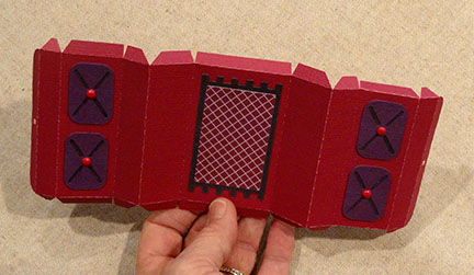
2. Identify the carriage box front (single circle symbol)
and the back (double circles). Prepare the carriage box
panels by bending back on all perforation lines and
tabs lines. Bend connector tabs at ends and near center
seam of front outward slightly.
Attach back window trim around window openings.

at center seam by overlapping straight edge of back
over the tab perforation line of front.

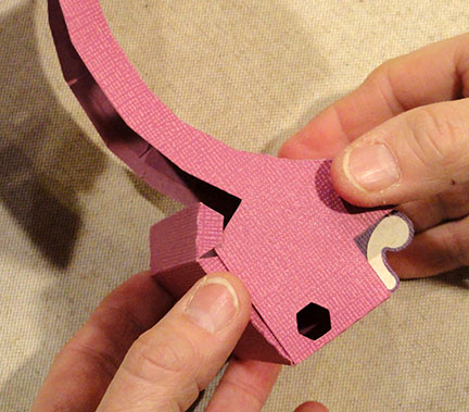
identifying the front end with the circle symbol cut
near the front top corner.

4. Line up the center bottom segment of the LEFT side panel
with the center tab of the front/back panel,
overlap the side straight edge to the tab perf line,
adjust to ensure edges are centered, then glue in place.
5. Working toward one end first, bend the perforated section
to line up each straight edge segment
with the corresponding tab perf edge, and glue each in place.
(NOTE: you may find it easier to join the top edge tab and
straight edge immediately after the center bottom edge,
then adjust the in-between tabs/edges to fit.)

6. Repeat the process for the opposite end
of the same side structure to connect straight
edge segments with tab perf edges.
Shown here is the first side completely in place.
7. Repeat the process to line up and attach
the RIGHT side structure.

8. Prepare the roof panel by bending back on
each of the section perforations, as well as
edge and end tabs.
Center and attach the 7 accent strips.

INTERIOR SEAT UNIT ASSEMBLY
9. Prepare the seat main panel by bending back edge
and end tabs, cross perf lines as shown
(these will follow the forward/back angles of the
side arch panel upper edges).
10. Layer the four cushion overlays and
contrast base shapes, then attach in position
on the seat back sections (match circle punches).
Attach the mini brad accents.
Layer the rug shapes, then center and attach in place
in the center section.
with the center tab of seat panel, and attach.

bend the center panel back, or forward, as needed,
to line up and attach each segment with corresponding
tab perf edge of side arch, until all tabs are attached.

13. Repeat the process of step 12 for the opposite
side of center panel and second side arch.
Here is a view of the completed seat section.
14. Bend the upper end tabs downward,
center bottom tabs inward.

end and center bottom tabs. . .

. . . then insert the seat unit into the interior of the
carriage box. Push downward to make sure the seat unit
is completely down and in place.
Apply pressure between sides, at ends and bottom
to help surfaces adhere.

16. Position the roof over the top of the carriage box
to overlap the roof end straight edge at the perf line
of the back end tab, and join.
Repeat for the front end tab and edge.
(Reach fingers inside through window openings
to help attach tabs, now and throughout assembly.)

and attach, then adjust the remaining edges and tabs
for the first roof side seam.
Repeat for the opposite roof side seam.

18. Prepare the accent side overlay by attaching
window trim shapes, oval and top teardrop.
Position overlay on top of carriage box assembly . . .

. . . line up the door and window openings,
and glue in place.
Repeat for the opposite side and overlay.

CHASSIS ASSEMBLY
19. Identify the chassis center panel front by locating
the tiny arrow triangle symbol.
Prepare the panel by bending forward on all cross
perforation lines, back on all side tabs.

20. Position the straight edge of center segment of
chassis side arch over the center tab of the
chassis center panel, and attach.
Bend center panel to continue to line up each
tab perf line at corresponding segment of side arch
until all are attached.

21. Attach back center panel (Q) at appropriate
end edge tab. Bend cross perforations to match
the contour of the footman seat, overlap straight
edge segments and tab perf lines, to attach
ONLY four sections.
(Remainder will be attached later.)

to center chassis end tab, then bend to align
and attach side arch segments to corresponding tab
perf lines, to attach ONLY four sections.

23. Prepare the footman seat scroll accents by
attaching offset inner shape on each side.
Insert back and bottom tabs into slots,
then bend back and glue in place on the inside.

back slightly on cross perf lines; bend end tabs back,
top tab upward.
Bend the lower in similar but opposite (forward)
fashion.
Place shapes back to back, align edges (except tabs)
while maintaining the curved form, and glue in place.

bend upward on the inside/backside,
and glue in place.
(NOTE that the "bottom" of this slot needs to remain
open to accept the yoke end if ponies team design
is prepared and attached.)

26. Bend under the bottom end tabs of front and back
center panel, and glue in place.

27. Complete the tabs positioning and attachment
for front end and back end.
CARRIAGE BOX TO CHASSIS ASSEMBLY
28. Make sure connector tabs on front, back
and bottom are bent perpendicular to carriage box.
Insert box into the arch cavity of chassis,
inserting bottom tabs into slots.
(Back and front tabs will rest on chassis front
and back structure, and be attached there.)


30. Attach end tabs to chassis top surfaces,
both front and back.

31. Prepare the connector tab covers by
bending forward to 90 degree angle.
Position, centered, over the tabs and
tab cutouts, and glue in place.

32. Bend long front/back tabs of chassis under
crossbar back and glue in place. Bend side end
tabs back to perpendicular.

with tab perf line aligned at center segment
of bottom arch edge, and glue in place
(tab behind chassis edge).
Repeat for opposite chassis side.

DECORATIVE ACCENTS
34. Position each door overlapping doorway opening
approx. 1/8" all around (NOTE bottom edge in
photo shows bottom edge close to side decor edge)
and glue in place (take care to apply adhesive
only where the two surface will connect).

35. Prepare the two step/overlay units by
bending step unit in half, end tabs upward. Glue the
backsides of step portion together (tabs remain free).
36. Insert the step through the decor shape slot
with shorter tab down
from the backside to the front, until . . .

. . . tabs perf lines align at slot edge.
Glue tabs to backside of decor shape.

chassis arch accents, matching edges, and
glue in place.

38. Position the arch accent on the appropriate
left or right side of chassis (extension points forward)
and insert the footboard tab through the extension slot.
Also line up the extension's inner cut edge at chassis edge,
with upper edge of arch offset slightly below
the chassis assembly edge as shown.

40. Position and glue the contrast extension over
the matching shape on the assembled chassis.

40. Position and attach the roof crown bracket
shapes to the backside of the
matching shapes.

WHEELS ASSEMBLY
41. Prepare the axle shapes by bending on
the long perforation lines as shown.

42. Form the axle into a tube to bring the long straight edge
to overlap the opposite tab to perf line, and glue in place.
NOTE it will help to wrap the tube around a length of
5/16" dowel to have a press-against surface.
(This size dowel will be cut to two pieces to
strengthen axles in later step.)
NOTE that there is a front axle with shorter end tabs,
and a back axle with slightly longer end tabs.

43. Prepare the wheel shapes for large back
and smaller front wheels.
NOTE that the inner wheel has the hexagon center
opening that will accept the axle end.
Outer wheel has solid center, with hub accent circle at center.
BOTH inner and outer wheels have accent rims.

44. Insert appropriate axle end (shown here is front)
through inner wheel from face side
to expose end tabs on the backside.

45. Position and attach an outer wheel assembly
over the backside of inner wheel, match edges
as exactly as possible, and glue in place.
(NOTE it will be helpful to place the axle assembly
wheel face side down on flat surface to apply
thorough pressure all around.)

46. Insert the remaining tab end of axle through
appropriate chassis hex opening, across to
opposite side hex opening, and through.

minus the end tabs (approx. 3 3/4").
Insert one section into axle tube.

48. Insert axle tabs through remaining inner wheel
hex opening, bend tabs back and glue in place.

49. Position and attach final outer wheel over
inner wheel.

face down on flat surface and press thoroughly to join.
(Repeat axle and wheel assembly for second axle.)

Here, at last, is the completed carriage model.


Does the instructions come in a print format?
ReplyDeleteSorry, no print format for instructions are available. You could try printing screen shots of this blog, if you need to.
ReplyDeleteThank you .. thats what I did was print of the page and it came to like 26 pages..lol There's something to keep my daughter busy!!
ReplyDeleteThank you..
Thanks a ton dear for sharing this Princess 3d Carriage Assembly Guide here. My daughter wants a royal themed birthday party this year so this Carriage would be a great thing to add in her party. I have just made the reservations for the best Chicago event space for this party.
ReplyDelete