
Classic pickup has truck-load of details
(shaped engine
hull with front grille and bumper, wheel fenders,
dimensional wheels with
dowel-reinforced axles,
cargo bed with accents, and more)
and is sturdy enough
for storage and re-use.
Cargo bed can hold store-bought or paper creation
Christmas evergreen to re-create a nostalgic memory
for mantle or shelf
display, centerpiece.
This project may require some dimensional
paper crafting
experience.
Measures approx. 11.75" long (including bumper)
x 6" tall
x 5.375" wide.

Pair it with "Countdown 3D Blocks for Pickup
Truck"
design and Fence 3D Cargo Bed for Truck
to help count down the days until Christmas.
Find the tutorials for the Blocks HERE, and
for the Fence sections HERE.
ASSEMBLY: 1. Identify and cut the shapes:
ENGINE HULL SECTION
A engine hull body main shape
B hull overlays (left, center, right)
C interior support
D front left & right wheel fenders with overlays
E front end build up (2) F grille
G front end base with headlamp extensions
H head lamp shapes (base red lamps 2 l & r;
chrome rim 1 l & r; lamp 1 l & r)
I front bumper and top overlay

 TRUCK BED SECTION
OO truck bed main shape
P truck bed liner accent
Q left & right outer accent overlays
R tail gate (outer) accent with frame overlay
(NOT SHOWN: chrome latch handle shape)
S inside side accent overlays l & r
T interior front, tail gate accent panels (2)
U back wheel fenders with overlays l & r
V wheel front (outer) shapes (4)
W wheel back (inner) shapes (4)
X wheel interior support (4)
Y wheel front overlays (4)
Z wheel whitewalls and hubcaps (4 ea.)
AA axle posts (2)
 CHASSIS SECTION
*BB chassis bottom layer
*CC chassis reinforcement top layer
(these shapes have been modified slightly)
DD chassis support boxes (2)
EE axle boxes (2)
FF running board with overlay (2)
 ENGINE HULL ASSEMBLY
2. Prepare the main engine shape by bending back
on all perforation lines for hull panels, tabs,
flanges, etc.


 Bend the front tabs in opposite directions
and glue in place on outside of front panel.
Bend the top tabs one in each direction,
and glue in place.

 10. Bend the hull bottom panel back into position
and insert support bottom tabs (pairs) through slots,
bend tabs in opposite directions.
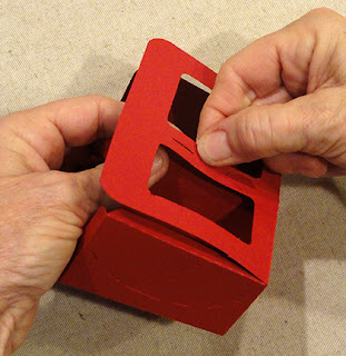
 11. Bend the side back flanges inward,
but leave the bottom extension un-folded.


 15. Position and attach headlamp units onto
front end accent extensions, aligning edges
that match up.


 19. Position and attach the top accent shape
onto bumper assembly top face.
 20. Insert the bumper tabs through slots from
front of grille accent shape. Bend tabs down
and glue in place.


CAB SECTION ASSEMBLY
23. Prepare the cab main shape and add-on
back panel by bending back on all panel, tab
and flange perforation lines.

 25. Bend the roof panel back to align flange perf line
and roof straight edge, and complete seam.

 28. Position and attach the door panel window
frame accents.
Also position and attach the window rims for front
and back window openings.

the door handle shapes in the cutout recesses.


 NOTE it is recommended whenever a stack of shapes
is glued together with liquid adhesive to use
a flat weight such as this fabric covered repurposed
free weight to press the stack to help avoid
warping, curling or other distortions, until the adhesive
is completely dry.


 37. Position the roof assembly over top of cab,
with cab top panel corners aligned with
the guide mark corners on roof underside
(roughly centered) and glue in place.

 FRONT fenders can be identified by a tiny "+"
symbol cut into the center outer tab
as indicated here.

 39. Bend the segment panel tabs back,
segments into position one at a time, to align each
with a corresponding straight edge segment,
and glue each in place . . .
 . . . along both arch halves.
Here is the left front fender completed.


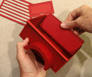
 NOTE the front end of the Bed shape can be
identified by a tiny triangle shape cutout in the
flange, as indicated by pointing finger.

 43. Locate the tiny guide mark cuts along
Bed side, then . . .

 44. Position and attach the outer accent shapes.


 46. Prepare the tail gate accent by positioning
and attaching the frame accent on top, with
offset margins all around as shown.


 . . . and side seams.


 52. Position each axle box at one end of chassis
assembly, with tabs inserted into slots, and
non-tabbed inward wall flush with support box.


 WHEELS & AXLES
54. Prepare axle tubes by bending back on
each perforation line.
 55. Form the axles, one at a time, into a tube,
using the 5/16" diameter dowel as a glue-against
surface, and overlap straight side edge over
opposite flange to perforation line, and glue
the long seam, moving finger pressure along length
until entire seam is secure, straight and smooth.
 56. Measure the dowel cut length by aligning
dowel end and tube ends even,
marking opposite tube end onto dowel,
then cut to size, one for each axle.
Cut dowels to length.


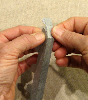
 61. Prepare the interior support strip by bending
center perf lines back, end tab back, top
and bottom tabs forward.
 62. Form strip into a square to join end seam.
 63. Position the support frame around the collar
stack, and join inner tabs to backside of wheel.
 64. Prepare the four inner wheels in same fashion
as outer wheels (steps 57-58).
Also push the triangle tabs at center hex opening
back, using a tool such as the handle tip of
this spatula to make sure the tabs are bending
inward on perf lines.


 Back the dowel out slightly to apply liquid glue
into the recess at collar hex sides, then . . .

 67. Prepare the wheel accent faces by centering
the hub cap chrome circle inside the white wall
circle shape, centered on the main (black) wheel circle.
Use a weight to help keep these layers flat.
68. When glue-up is dry, position and attach
wheel accent assembly onto the front of two wheels
that are attached to axles.
(Remaining face accents will be attached later.)

 . . . and through box to exit opposite hex opening.


ENGINE HULL SECTION
A engine hull body main shape
B hull overlays (left, center, right)
C interior support
D front left & right wheel fenders with overlays
E front end build up (2) F grille
G front end base with headlamp extensions
H head lamp shapes (base red lamps 2 l & r;
chrome rim 1 l & r; lamp 1 l & r)
I front bumper and top overlay

CAB SECTION
J cab main section
K cab back panel add-on with window rim
L door overlay l & r with window rims
(NOT SHOWN: chrome door handle shapes)
M interior opening cover
N roof & rim base shape (note this shape
was modified after model was built)
O roof top build up layers (3)
P wheel interior post collars (4 sets of 4 ea)

OO truck bed main shape
P truck bed liner accent
Q left & right outer accent overlays
R tail gate (outer) accent with frame overlay
(NOT SHOWN: chrome latch handle shape)
S inside side accent overlays l & r
T interior front, tail gate accent panels (2)
U back wheel fenders with overlays l & r
V wheel front (outer) shapes (4)
W wheel back (inner) shapes (4)
X wheel interior support (4)
Y wheel front overlays (4)
Z wheel whitewalls and hubcaps (4 ea.)
AA axle posts (2)

*BB chassis bottom layer
*CC chassis reinforcement top layer
(these shapes have been modified slightly)
DD chassis support boxes (2)
EE axle boxes (2)
FF running board with overlay (2)

2. Prepare the main engine shape by bending back
on all perforation lines for hull panels, tabs,
flanges, etc.

3. Bend the rounded-top front panel back and
adjust the near-center hull segment so that
the wedge tab perf line aligns at corresponding
edge segment of front panel, and glue in place.
4. Continue along the same front panel edge to adjust
and align the next hull segment tab to hull, etc.
Repeat until three rounded edge tabs are attached
to front edge, as well as the longer side edge
aligned and attached to front panel side edge.
5. Repeat for the opposite half of the hull
and front edge tab-to-edge attachment sequence.
NOTE: the hull bottom panel remains unattached
at the point in the assembly

6. Prepare the interior hull support by bending
the shape in half, allowing the embedded tabs
to extend away as shown.

7. Fold the support shape in half, and glue together
the panel sides leaving all tabs unattached . . .

. . . so the pairs that align can be independently
bent away from each other, as is shown here
with the bottom pair of tabs.
NOTE: tabs will be folded together to be inserted
into the appropriate slots during next steps.

8. Orient the support shape to match the angled
upper edge with the hull slanted top, then
insert into the hull cavity . . .

. . . to insert the top (single) tabs into the slots
on top, and the front (paired) tabs into
the hull front panel slots.

and glue in place on outside of front panel.
Bend the top tabs one in each direction,
and glue in place.

9. Identify the bottom panel inward corners and
the nearly alignment dash cuts:
this extension beyond dash cuts is NOT a flange
that should be bent, but an extending panel
that will eventually fit under the cab assembly
and be glued in place.
DO NOT bend it back.

and insert support bottom tabs (pairs) through slots,
bend tabs in opposite directions.

At the same time, position, align and attach
the hull side bottom flanges (which have been
bent inward), taking care that the panel is
forced toward the back as completely as possible,
with the extension dashes visibly beyond side walls.

but leave the bottom extension un-folded.

12. Prepare the top hull accents by bending back
slightly on the perforations, then position and
attach over the corresponding angle perforations
on hull, with offset at edges as shown.

13. Identify the light accent shapes:
top: lamp circles
middle: chrome "rings"
bottom: headlamp base pairs for build up stack
14. Position lamp circles centered on chrome circles.
Stack and attach base pairs.
Position, offset, and attach lamp/chrome units
slightly off-centered toward the rounded end
of base stack shape (see next frame, top left).

front end accent extensions, aligning edges
that match up.

16. Prepare the dimensional bumper by bending
back on all perforation lines for narrow panels, tabs.

17. Bend the front face panel down, bend the side
extension boxing into position so that tabs slide
under the top panel, and tab perf lines align at
top angle edges. Complete for both ends.

18. Also bend the back end boxing panel around
the corner and join the tab under top panel
in same manner.

onto bumper assembly top face.

front of grille accent shape. Bend tabs down
and glue in place.

21. Layer the frame-only grille under-stack shapes
behind the grille/bumper assembly with edges aligned,
and glue in place. (This provides strength and also
allows a little separation and space behind grille.)

22. Position the grille/bumper unit onto front of
front end base with corresponding edges aligned,
and attach layers together.
(Set aside until the rest of truck assembly is completed.)

23. Prepare the cab main shape and add-on
back panel by bending back on all panel, tab
and flange perforation lines.

24. Bend side panels back, and bend front upper panel
back to align the upper front edge with side
wedge flange, and glue seam.

and roof straight edge, and complete seam.

26. Bend the bottom panel into position
and complete seam.
27. Repeat steps 24-26 for the opposite side seams.

frame accents.
Also position and attach the window rims for front
and back window openings.

29. Position and attach the door accent units
onto each side panel of cab assembly.
Though not shown here, position and attachthe door handle shapes in the cutout recesses.

30. Position the engine hull assembly at front of
cab and insert back tabs into cab slots, work tabs
fully through to inside, then bend downward
and glue in place on cab inside.

31. Apply adhesive (tape recommended) to inside
cab cover panel, then insert through cab back
opening, center over the openings that access
engine hull, and attach in place.

32. Bend the cab back and bottom flanges inward,
bend back panel into position to align straight edges
with flange perforation lines, and join the three seams.

33. Prepare the roof reinforcement/build up shapes
by layering and attaching, taking care to align
all cut edges as precisely as possible.

is glued together with liquid adhesive to use
a flat weight such as this fabric covered repurposed
free weight to press the stack to help avoid
warping, curling or other distortions, until the adhesive
is completely dry.

34. Prepare the roof unit by bending back on all
panel or boxing edge perforation lines, and at tabs.
NOTE changes in appearance in roof file shape
here and throughout the roof assembly steps.

35. Bend the front, sides and back boxing
sections down.
Bend the front boxing rim tabs back and under
the roof edge, bend to align tab perf lines
with roof front straight edges, and join
tabs with each segment.
36. Bend the tiny corner tabs back,
position and attach boxing wall straight ends
over corresponding tab perforation lines
to form a roof "tray".

36. Position the roof tray under the roof build up stack,
with outer edges aligned as precisely as possible,
and glue in place.

with cab top panel corners aligned with
the guide mark corners on roof underside
(roughly centered) and glue in place.

38. Prepare the fender (wheel cover) shapes left
and right, front and back pairs,
by bending back on arch segments
and inward tabs. NOTE it may be helpful
to leave the arch segment outer tabs un-bent
to assist with insertion into slots.

symbol cut into the center outer tab
as indicated here.

Also identify the "back" end of the attached arch
shape (shown by pointing finger here)
which has the more acute or pointed shape.
This is important for positioning the correct fender
onto the hull assembly.

segments into position one at a time, to align each
with a corresponding straight edge segment,
and glue each in place . . .

Here is the left front fender completed.

40. Position the appropriate fender at the hull
panel with the arch slots, then insert each tab
carefully into corresponding slot until fender
body is flush with hull. Bend tabs downward
on hull inside and glue in place, including the
"solo" tab that is inserted into the cab interior.

NOTE: front-most tab does NOT have a slot,
but instead is bend inward and glued to hull.

CARGO BED ASSEMBLY
41. Prepare the cargo bed main shape by
bending back on main panel division perforation lines.
At front and back center edges, bend flanges back.

On side edges, bend the outer "rim"
perforation line BACK,
and the next two perforation lines FORWARD.

identified by a tiny triangle shape cutout in the
flange, as indicated by pointing finger.

42. Form the Bed shape into a "tray" by bending
sides, front and back into position, flange tabs
bent inward. Align straight edge with flange perf line,
and join the four corner seams.

Bed side, then . . .

. . . apply glue to underside of the rim section,
then push the rim inward to attach to outer face
of Bed wall, with bottom rim edge aligned
at guide marks.


45. Position the appropriate left or right back
fender assemblies at Bed sides, then insert
tabs through slots as previously done for
front fenders.

On bed inside, bend tabs downward and glue
in place.

Bend the back end bottom tab under and glue
in place as with front fenders.

and attaching the frame accent on top, with
offset margins all around as shown.

47. Position and attach the interior accent
"covers" or shapes to sides, front and back.
Also position and attach tail gate on outside back,
and bottom "liner" in bottom of Bed.
(Though not shown, also position and attach
the tail gate handle shape in the panel recess.)

CHASSIS PREPARATION & ASSEMBLY
48. Prepare the axle box (left) and support box
by bending back on all panel and tab perforation lines,
except, on support box, outer-most flanges
will bend forward.

49. Form the support box into a tall narrow
form with flange tabs inward, then align and glue
bottom . . .


50. Position chassis main (bottom layer) shape
face downward. Insert support box through
the cut out rectangle opening, and push through
until flange perforations align with opening edges.
Apply adhesive to attach side and end flanges
in place to chassis back side.
NOTE the chassis layers have been slightly modified
from those shown in assembly model.

51. Prepare the axle box in similar manner,
bending ends and sides back to align and join
corner seams for form a tray.

assembly, with tabs inserted into slots, and
non-tabbed inward wall flush with support box.

On underside, bend tabs outward and glue in place.

On front make sure that end tab is tucked under,
then glue in place, while also . . .

. . . applying glue between support and axle boxes
where walls touch. Apply pressure to all areas
being glued until secure.

53. Position chassis top layer over main assembly
with outer edges aligned where they match,
and glue securely in place.
(Turn assembly top-side down, and use
weights as needed to assure flat joining.)

each perforation line.

using the 5/16" diameter dowel as a glue-against
surface, and overlap straight side edge over
opposite flange to perforation line, and glue
the long seam, moving finger pressure along length
until entire seam is secure, straight and smooth.

dowel end and tube ends even,
marking opposite tube end onto dowel,
then cut to size, one for each axle.
Cut dowels to length.

57. Prepare the outer wheel shape by bending
back on all perforation lines.

56. Bend boxing section tabs back so they will
tuck under the "round" wheel shape . . .

. . . then bend boxing to perpendicular to align
each "round" segment straight edge with
corresponding section tab perf line, and joining
the 3 segment seams

57. As each sequence is completed,
apply glue to the end tab . . .

. . . then bend the next
sequence strip into position to join straight end
over tab perf line.

58. As final sequence seams are completed,
also tuck the end tab under the lead sequence
straight end and join that seam as others
are joined.

59. Prepare the axle collar stabilizer stacks
by layering the four duplicate shapes and gluing
together, taking special care that the inner edges
of the hexagon opening are aligned as precisely
as possible. Use weight to keep flat during drying.

60. Position one collar on the inside of each outer
wheel, making sure hex openings align.

center perf lines back, end tab back, top
and bottom tabs forward.


stack, and join inner tabs to backside of wheel.

as outer wheels (steps 57-58).
Also push the triangle tabs at center hex opening
back, using a tool such as the handle tip of
this spatula to make sure the tabs are bending
inward on perf lines.

65. Apply glue to support tabs . . .

. . . and to outer side faces of inner wheel. . .

. . . and to face of triangle tabs at center opening,
then . . .

. . . fit the inner wheel inside the outer wheel,
using a blade tool as needed (this is a snug fit)
and slide the wheel components together fully.
Apply pressure to all areas where glue was applied.
but move quickly onto the next step.

66. Insert one end of axle assembly into inner wheel
opening and push in fully . . .

. . . taking care that end seats into the collar opening.

into the recess at collar hex sides, then . . .

. . . reinsert fully until dowel end is flush with wheel front.

the hub cap chrome circle inside the white wall
circle shape, centered on the main (black) wheel circle.
Use a weight to help keep these layers flat.
68. When glue-up is dry, position and attach
wheel accent assembly onto the front of two wheels
that are attached to axles.
(Remaining face accents will be attached later.)

69. Attach the wheel/axle assembly to chassis
by inserting axle end through axle box hex opening
(try to find the orientation of wheel that will put
a straight edge as "flat" for top and bottom positions) . . .


70. Follow the process in step 66 to insert and
attach each axle to second wheel, front and back.

FINAL ASSEMBLY
71. Position the front end/cab assembly over the chassis
with edges aligned with top chassis layer edges,
and centered, and attach in place.
NOTE it may be helpful to use a quick grab glue
such as Fabri-Tack, along with folio clips, clothespins,
etc. to help these layers adhere properly.

72. Position the cargo bed assembly behind
the front assembly attached to the chassis assembly,
center, then glue bottom and front panel in position.
Follow the "NOTE" advice in previous step.

73. Prepare the running board main shapes
by bending back on the middle perforation line.
74. Position and attach the rim overlay shape
at corresponding (top) rim portion of running board.

75. Position the running board along side of truck
with bottom angled flange sliding under the chassis,
with rim extending upward and perpendicular,
with ends overlapping the fenders.
Glue in place where surfaces overlap (under chassis,
on fenders).

76. Bend the back fender connector tabs
forward at center perf line, then position as shown
at the fender edge and onto the chassis surface
next to it. (This shape will help stabilize and join
fender to chassis.)

77. Position and attach the front grille/bumper
assembly.

Here are more views of the completed truck.


I've spent the last 1 1/2 day in quarentine buliding this truck! It turned out great! Many parts so I got some training of my brain though…
ReplyDeleteThanks for a great build!
Hi. could you tell me what size did u cut it out in the silhouette. I'm lost on how to print all parts at the correct sizes. I'm new with this projects.
DeleteThank You if you could reply or send me an email at
yolilove77@gmail.com
When using the svg files that are purchased and downloaded from the Silhouette America online store for use with their Cameo system, the shapes will open at their correct sizes.
DeleteWhere can the template for the 3D truck be purchased...Thanks
ReplyDeleteThe svg cut files are available for Silhouette America's Cameo system through Silhouette America's online store.
DeletePlease, please can someone help me? I recently purchased this file from Silhouette Design Store. I purchased the SVG version as I have a Cricut machine. When the file is imported into Design Space, the entire grouped image only measures 11.944 (W) x 16.523 which is no way big enough to produce the stated finished measurements.
ReplyDeleteCan someone please offer guidance as to the correct size these images should be?
Thank you
If you are using Silhouette's software, they should import or download at the accurate size. If you are using Cricut software and machines, this often has been a problem, but you will need to get advice about this from Silhouette America, if that is where you are purchasing the file. We cannot offer any support for the difficulty of importing our designs to Cricut or other systems. So sorry.
DeleteWhere can i get the truck pattern or template please
ReplyDeleteThe cut file svg is available for purchase for the Silhouette Cameo system through Silhouette America's online store.
ReplyDeleteI have a Cricut Maker and have the same problem. How do I resize this to make it work on design space?
ReplyDeleteI am afraid I can offer you no help with using our files purchased through Silhouette America on your Cricut Design Space machine. I suggest contacting Silhouette America, who I believe are still claiming that when you purchase the svg file versions, you will be able to use them with DS. Our experience with the unreal amount of customer service needed by Cricut users to use svg files, or other formats with their machines is what drove us out of business on our own. We kept working and finding work arounds, then Cricut would change things so our designs would not work. Not worth it for us.
ReplyDeleteI have this file and use Silhouette studio. When I open the file the entire file that is grouped together is 33.857 wide and 46.836 high. I do not use design space so i have no idea how files open/import but I hope this helps those with size issues in Design Space.
ReplyDeleteCan i cut this on my Cricut Maker
ReplyDeleteIf you have purchased the cut file from Silhouette America, they claim that you can cut the svg files across many if not all different kinds of machines. As you may have read in previous comments for this design or others, we have had bad luck with Cricut's software not using our svg files in the easy way that the Silhouette America cutting machines do. I cannot offer the service support you may need, but Silhouette may be able to.
Delete