Showing posts with label hanging lantern. Show all posts

Thursday, March 31, 2022

Lantern 3D with Floral Decorations


Confection-colored details adorn four outer panels 
of this acorn-shaped vessel which encase the inner lantern hull. 
Bracket edge flanges add style at upper and lower angled edges. 
Thread wire or ribbon through center, add beads or tassel 
at bottom end, fashion hanging “eyelet” at top.
 Add interior magic by attaching a dangler of some kind, 
such as the “Egg 3D Hollow Ornament”, 
“Egg 3D Slice Form Ornament”, or 
two-sided “Cross Scroll Ornament” separate designs. 
Enhance holiday decor by hanging from chandelier, 
archway, high shelf or other appropriate location. 
Lantern measures approx. 8.25” tall x 4.25” wide when assembled. 

ASSEMBLY: 1. Identify and cut the shapes:
For the inner hull -
A hull two-wall sections (2)
B end collar reinforcement inserts (2)
Not shown: end [repairing] reinforcements (2)
For outer wall panels with decorations - 
C outer wall panels (4)
D decorations (4 sets), including:
left & right edge trim sections for upper, middle, lower
end brackets for top & bottom
stem rectangles for top & bottom
edge trim for center window opening, crown trim
double-tipped stems, blossoms & sepal overlays
with mid-side flourishes
three-hole "pop tabs" for left and right
2. Prepare the inner hull sections by bending back on
all perforation lines except the end collar shapes
at top and bottom.
3. Bend the top trapezoid panels back to align straight
side edge and overlap to match up with flange's
perforation line, and glue seam.
Repeat for bottom panels.
4. Bend the end stem rectangles to perpendicular,
overlap straight edge across adjacent tab and join.
Repeat for both ends.
5. Orient the two hull half sections to align and join
two side seams, plus . . .
. . . two upper angled seams and 
two lower angled seams, plus . . .
. . . and two upper & lower stems.
6. Bend the side walls of the reinforcement collar inserts
forward/up, apply glue to underside/outside of walls,
then insert backside-down into the square
opening. Slide down until . . .
. . . top wall edges match to hull top edges,
then apply thumb/fingertip pressure at each wall
until firmly in place.
7. Plan and devise a hanging method.
This may include narrow ribbon that can attach an interior
dangling object just at top, or from bottom with a tassel end,
two ends up through lantern interior -- including through
dangler -- then through top to form a hanging loop or
attach to a decorative hook.
NOTE: the ribbon or wire or other center mechanism can be
completed after the outer walls are in place.
However, it may be easier to manipulate and handle
before the walls are in place.

THE PROJECT MODEL USES A WIRE.
A) Form an open end loop/hook at one end of a length
of 16 gauge or equivalent wire which becomes bottom end,
then attach tassel or other bauble, then close loop.
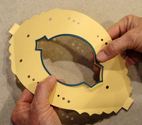
B) Lay wire assembly across top of hull, with end loop
in place where it will stop at bottom stem hole opening.
Measure up wire to approx. position where you desire
bottom of selected dangler to be in finished assembly, 
and mark wire.
This image shows the slice form egg ornament as dangler,
held in place to help determine bottom measurement.
C) Form a cork screw "knot" just below the length
that has been marked. This change in the wire is
intended to stop the downward slide of the dangler egg
on the axis of the wire.
D) Insert the wire through bottom of lantern, turning
the wire so that the cork screw turns the punched hole,
while at the same time threading the egg's center tunnel
from bottom to top. Continue inserting the wire through
the top collar platform, then adjust as needed to help
the wire get to the final positioning.
E) At top, carefully use tool(s) to form a top hanging loop
and cutting away excess length.
8. As needed, position and glue in place 1-2 end
"repair" or reinforcement squares at bottom
and/or top collar platform, torqueing to allow the cut
split to open so it can be slipped around wire
or ribbon. Rotate the second (etc.) square so that
the split lands in a different direction from previous.
9. Add some slight back curl to each of the outer wall
shapes: turn panel face down on work surface,
then use a rod tool such as this 3/16" dowel
to press the shape in place while panel is drawn
up from under the tool.

10. Bend angle edge bracket flanges forward (valley)
and end "tabs" forward at top and bottom.
11. Add back curl to long decor shapes that will be
added on front of each panel, so that they will stay
adhered in place. 
Then position and glue in place.
Shown in these two frames is the window trim shape.
Add the "crown" accent at the top (narrow end)
where it hugs the top of window trim.
Add the end rectangles and brackets,
"pull tab" shapes where they can "register" at
tri-hole cut out positions.
Prepare the double-tipped stems by attaching
the corresponding small or large blossom overlays,
then the sepals at bottom of blossoms.
Position and attach in space between window trim
and pull tabs, with the center angle centered between
ends of pull tabs.
Position and attach the side "crown" accents centered
and offset on outside of stem center angle.
Finally, add the panel trim shapes at angle edges
upper and lower, and arch side trim shapes.

12. Curve the first completed outer wall panel around
the hull, then position and attach top stem end to stem panel
of inner hull. (Use a quick-grab glue such as Fabri Tack,
to attach ends securely.)
Once one end is securely in place, "wrap" or curve
the panel around the hull to position and attach
the other end in place, gently urging angled perf lines
to match up with the perforation corners of inner hull.
13. Repeat Step 12 to position the next panel,
position and attach first end . . .
. . . then second. As subsequent panels are positioned
and joined in place.
As previously noted, urge the ends into position
to duplicate the end stem panels.
NOTE that the angled bracket flanges
should line up and be glued together as part of the
"adding panel on" process.
14. Continue to add final two side panels in place,
aligning, adjusting, securing and attaching bracket
flanges as done before.
15. Finally, add finishing touches, including
for this wire-center version, a ribbon tied in knot
and bow. (For a ribbon center, consider adding
decorative or painted beads onto the ribbon at stem ends,
or other appropriate decorations of choice.
Here is the completed lantern with slice form
egg dangling inside.


Sunday, April 22, 2018

Lantern 3D Hanging for Votive Tea Light

Miniature rectangular lantern is sized to hang 
from the "Flower Wreath Stand"  (view that project HERE).
A modified arm for stand included in the file.
Lantern measures approx. 3.75 wide x 3.75 deep x 7.5" tall 
(including hanging loop). Show-thru "grille" panels hull, 
has reinforced at corners with square posts 
(insert .25" cut-to-size dowel lengths into posts for strength).
Hull fits into bevel-edge base.
Slightly-domed top fits into dimensional rim and connects 
to top of center column and hanging loop. 
Back grille swings open to allow 
access to interior. Inside the lantern, 
an octagonal "candle" column holds a small battery
votive (standard 1" diameter), 
with optional wax-catcher octagon cup underneath. 

ASSEMBLY: 1. Identify and cut the shapes:
A hull (main) wall sections (2)
B wall overlays (6)
C back wall overlays (2)  D latch nib strips (2)
E opt. corner posts (4)
F base shape (NOTE this has been modified)
G base bottom opening cover
H interior platform
I top rim
J top dome (NOTE this has been modified)
K top column   L hanging loop assembly (2 ea of 2)
M front grille window overlay
N side grille window overlay (2)
O back grille overlay with nib slots
P optional modified display post arm, reinforcements
Q candle column    R wax catcher
2. Prepare the base shape by bending back
on all panel, wall and tab perforations.
3. Bend adjacent walls back to perpendicular
position to bring straight side seam edge to
overlap opposite tab to perforation, and glue
lower portion of side seam. 
(Eventually complete for all 4 corners.)
4. Bend bevel wall panels inward to align straight
seam edge at tab perf line, and glue upper seam portion.
Repeat for all 4 corner bevel seams.
5. Prepare the main hull wall sections by bending
back at center vertical perf line, at flanges and
tabs.
6. Join the two wall sections by overlapping
the straight edge of one over the corresponding
side tab perf line, adjust for alignment of
top and bottom of wall panels, and glue seam.
7. Layer pairs of wall overlays and glue together,
taking care that all inner and outer cut edges
are aligned as precisely as possible.
NOTE it may be helpful to press the glued-together
shapes under a flat weight during the glue drying
process in order to prevent curling or warping.
8. Layer and glue together the two back wall
frame overlays similarly, taking care to line up
the nib slots in the lower corners.
9. Prepare the nib strips by bending back at
the center perf cut, and forward at the two
side perf cuts, so that the strip sort of forms
a letter 'M' shape.
10. Glue the center two segments together
to create an inverted 'T' shape. Side segments
should remain free to act as side tabs.
11.Insert the nib tip through the wall overlay
slot from the back side and push in fully
until side tabs rest against back of wall.
Glue tabs in place. Repeat nib on opposite side.
12. Position the two-layer wall overlay on the back
panel of the main hull assembly, matching
inner edges as exactly as possible, and glue in place.
13. Position and attach the other "regular" wall
overlays onto the remaining wall openings
in the same fashion.
14. Prepare the back wall grille  by bending
forward along the top segment perf line
to form a narrow "hinge" flange.
15. Position the back grille over the back
panel so that the grille's slots fit over
the nibs, match the inner frame cut edges
of window opening and the grille frame opening edges,
then  glue the flange in place above the window opening.
NOTE it may be helpful to place a flat weight
along the hinge area to keep it flat while drying.
16. Position the two side grilles over the appropriate
hull panels, with the front circle grille over the
middle panel (which will end up opposite the back
when the hull is completed).
ALTERNATELY you can use 3 lattice grilles
and omit the circle panel. Flatten with weights
while drying, if possible.
17. Form the hull into a tube to overlap the straight
back edge over the opposite flange, and complete
side seam.
18. Fit the hull bottom edge (with long flange)
into the top opening of the base assembly,
and direct the base's side tabs into the corresponding
slots of the hull. NOTE using a thin blade tool
such as a spatula or fingernail file to help ease
the tab lead edges under the slot edge, until . . . 
. . . the hull is inserted fully and flange perforation
crest rests on bottom of base.
19. On the inside of hull, bend the tabs
downward and glue in place to the back inside
of hull walls.
20. Prepare the platform shape by bending back
the side flanges, and also bending downward
the tiny triangle tabs at each inset corner.
21. Apply glue to the inside surfaces
of the hull assembly . . . 
. . . then insert the platform into the hull from top . . .
. . . and gently work the platform downward
until side flanges rest on the base bottom surface.
Apply pressure to the sides to attach in place.
22. Prepare the optional post shapes by bending
back on the long perforation lines between
wall panels and along edge flange.
23. Form the post shape into a tube to overlap
straight edge to long flange perforation line,
and glue in place.
NOTE it may be helpful to use the .25" dowel
as a form to wrap the post shape and help
join the side seam.
(The square post can also be pressed flat
to overlap edge to flange perf line
and complete seam that way.)
24. Measure the lengths of optional .25" dowel
by pushing the dowel end even with tube end
(on the left in this image), then marking 
the opposite edge of the tube position on the dowel.
Use wood saw to cut across (perpendicular).
Cut dowels for 4 posts.
25. Apply glue to the inward two edges as shown in
the image below. Then position a post at 
interior corner of hull, with pair of end tabs toward 
the center, and insert end through the square 
opening at the corner, and push down fully . . . 
. . . until the bottom of post (tabs) rest against
the base bottom surface, and the top of tube
and dowel are even with the top of the hull).
Apply pressure to appropriate areas to
keep post surfaces tight in corner surfaces.
Position and attach remaining 3 posts.
26. Prepare candle column by bending back
on all perforation lines, except the top 7 flange
tabs bend forward/upward.
27. Form the candle column into a tube
to position and join the side seam.
28. Bend the bottom cap into position
and adjust so that tab perf lines line up
with the octagon cap edges, and glue in place.
29. Prepare the wax catcher shape by bending
back at inward perf lines of edge flanges,
also bend forward at wall base perf lines
and side wedge tabs.
30. Bend the wall straight side edge to overlap
adjacent wedge tab to perf line and complete
first side seam. Repeat the positioning to join
the remaining 7 side seams.
31. Bend the outer side flanges (walls) down
and glue in place around outer cup surfaces.
32. Position bottom of candle column into
wax catcher cup, center and glue in place.
33. Insert the candle/cup assembly into hull
interior to center and glue bottom of cup
to platform.
34. Prepare the top rim shape by bending back
on all walls, flanges, and inward opening flanges.
35. Re-bend the window flanges outward/upward
to allow for wall construction.
36. Bend two adjacent walls back to align straight
side edge over tab to perf line and complete seam. 
Complete remaining side seams.
37. Fit the top rim over the tops of hull walls
and fit tabs through slots.
Bend tabs toward center and glue in place.

38. Prepare the top dome shape
by bending back on all perforation lines for
walls, dome sections, lid center triangle tabs.
39. Bend the first two adjacent walls back to
align the bottom segment straight edge
overlapped to opposite tab perf line, and glue seam.
NOTE: the bottom edge tab extensions
visible in these images were designed OUT
of the final version of the dome shape.
Please disregard.
40. Bend top segments back to position
and complete that part of seam.
Complete the two-part seams for remaining corners.
41. Bend top panel (lid) down into position,
adjust and glue edges to flanges beneath.
42. Prepare the hanger loop by bending
bottom tabs outward on front and back shapes.
43. Position the non-tab inner shape over
the inside face of front hanger loop,
work to align inner and outer curved edges
as precisely as possible. Join second
inner shape onto assembly, then . . . 
. . . add back
shape over the assembly, matching edges
as precisely as possible. Use flat weight
to keep flat during drying.
44. Prepare the top column shape by bending
back on all panel and flange tab perf lines.
45. Insert bottom tabs of hanger into roof slot . . . 
. . . then bend tabs back and glue in place
to the underneath surface of roof.
46. Bend panels into position to complete
the four side seams.
47. Insert the bottom end of the column assembly
through the dome top opening and push down
into position until . . . 
. . . tabs are exposed at bottom. 
Bend tabs outward and glue in place.
NOTE: the side tabs that are visible as outlines
in this image have been designed out
of the final file version. Please disregard.
48. On the topside, depress the dome roof slightly
on each side to apply glue on the center column surface
so that it will attach to the dome's opening triangle tabs.
49. Fit dome into top rim recess and
gently work downward until dome is fully down.
Glue in place.
50. Open back grille by unlatching nibs
from slots, position tea light into top
of candle column, then re-close grille
and latch nibs into slots.
Here is the completed lantern.
51. To use with the "Wreath Display Stand",
prepare and replace the original arm
with the shorter arm shapes included
in the lantern file.
This shorter arm will keep the weight center
of the lantern closer in to the post to prevent
undesired tipping.
(This image was taken on the original arm.)