
Bring
an icon of the Netherlands countryside home
with miniaturized replica of
a
classic rural power machine.
Dimensional model has eight-sided hull
with rim
base, middle platform,
interior square support beams
(with 5/16" wooden dowels inside for strength),
shaped roof
with corrugated accent overlay,
angled prop beams and layered blades (sails).
for decoration options.
Measures
approx. 10" tall x 5.75" (without flywheel and sails).
ASSEMBLY: 1. Identify and cut the shapes:
A main hull shapes (2)
B hull accent shapes (8)
C post shapes (2)
D hull base shape
E rim shapes (2)
F platform G platform accents (8)
H platform support wedges (8)
I arch roof main section J opt. arch front overlays (2)
K corrugated roof panel
L direction cross beam arm,
tail fin build up shapes (8), and
accents (2)
M reinforcement (interior) collar
N optional rim accents (8; not used on this sample)

O flywheel arm half sections (8)
P dimensional sail arms (4)
Q sail paddle base shapes (4)
R sail front build up overlay shapes (96 + 24 face)
S sail back build up overlay shapes (36)
T flywheel pivot box U support strut
V flywheel arm brackets build up (2 sets of 5)
W hub front face (2)
X hub back layers (with cutout for brad prongs) 3)

2. Prepare the hull main shapes by bending
back on all panel, side flange, and bottom tab
perforation lines.

edge over the corresponding side flange tab
to complete the side seam.

4. Position accent shapes with even offset
at sides and top edge (bottom edge has wider
offset margin where base rim will cover),
and attach in place.

(8) accent rib shapes can be cut instead,
bent back along center perforation lines,
then positioned and attached at top of each panel
corner angle. (Wait to attach these until hull second
side seam is completed.)

5. Form the hull into a tube to bring together
straight side edge and flange edge, overlap
and complete second side seam.

6. Prepare the reinforcement collar shape
by bending side flanges forward.

then carefully insert into the bottom opening . . .

flanges are approximately 1/4" above and
parallel to hull tab lines, and glue in place

perpendicular angle.

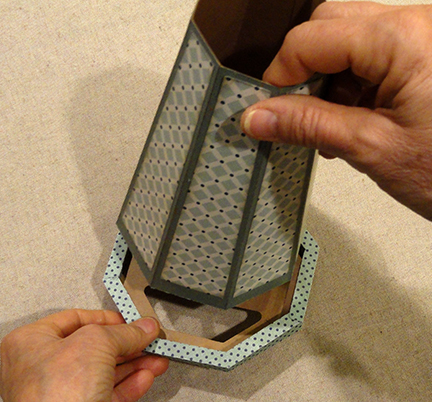
9. Prepare rim shapes by bending back on
all panel, flange, side perforation lines,
bending inner tabs forward.

aligning panels, overlapping straight side edge
over corresponding tab to perf line, and
joining to complete first side seam.

11. Position base octagon shape edge segment #1
over first flange tab backside and adjust edge
to be along flange perforation line, base corners
to line up with ends of rim segment,
and glue in place.

this image shows how the rim segments
will eventually be "curled" inward with inner tabs
inserted into the corresponding slots cut in the base.
But for now, leave the rim segments "uncurled"
or open.

12. Continue to bend the rim shape around
the base octagon, aligning and gluing each
rim flange at corresponding base edge,
until the final segment remains.
Position the final segment while at the same time
inserting the side tab under the opposite straight
rim side edge, then glue both flange and tab
in place in one step.

13. Curl the first rim segment inward to
insert the tabs into corresponding slots in base.

On underside, bend tabs toward center
and glue in place on base.

inward and into position, one by one,
first applying adhesive as described
in this image, until all segments have
been positioned.
NOTE: the final segment will be difficult
to tuck tab and overlapped rim corner;
wrap both ends as top layers.

15. Apply adhesive to the hull bottom tab
outward surfaces, then . . .

inside the rim of base assembly.
Apply pressure until joining is completed.
16. Prepare the platform shape by bending
inner tabs back, octagon wall panels forward,
outward wall faces back.

angle to overlap short straight edge over
adjacent tab, and join seam.
Repeat for remaining 7 segment seams.

18. Bend each wall face downward to cover
joining seam tabs, and glue in position.
19. Position and attach optional face accents.


and slide down into position approx. 2"
above hull bottom edge. Hold in place
until securely attached to hull.

21. Prepare the platform support wedges
by bending back on both perf lines,
then forming the shape into a triangular tube,
overlapping the straight bottom edge over
the tab to perf line, and gluing in place.

in line with hull panels, joining under platform
with adhesive attaching top and back surfaces
to platform and hull.
23. Prepare the post shapes by bending back
on all panel and flange perforation lines.

bring the straight side edge over the opposite
long flange to perforation, then joining.
NOTE: it will be helpful to use the 5/16" dowel
as a form to wrap the shape around so that
pressure can be applied all along the post shape
during the gluing process.

25. Measure the dowel to post length (with bottom
tabs bent outward, dowel even with top edge,
and mark for cutting. Cut two dowel inserts,
then insert into post tubes and glue in place.

26. Insert the top end of post assembly
through the base post opening, through
corresponding cutout of collar, then fully in . . .

. . . so that post tabs are flush with base,
Glue tabs in place.

27. Place hull assembly flat on working surface,
adjust post position to be as perfectly
vertical and perpendicular as possible,
then glue in place to inner wall of hull panel.
Repeat for second post.

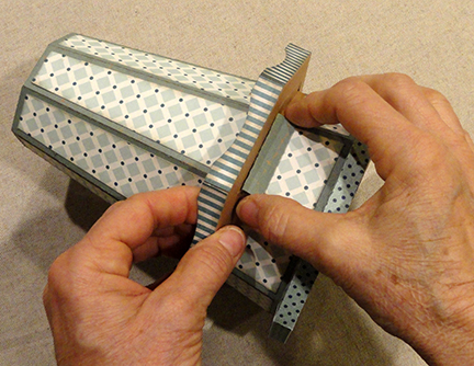
28. Prepare the direction cross beam shape
by bending back on all panels and flange tabs.

straight side edges over tabs to perf lines,
and glue in place.

the five build up shapes with edges and punch holes
carefully aligned, then glue layers together.
Create two fin build up shapes.

NOTE: for fin and other built-up shapes, it will
be helpful to use a flat weight to apply pressure
during the glue drying process, such as this
fabric-covered re-purposed free weight,
to help prevent warping and curling of the shape stack.
(Shape shown in this illustration image is for
the sail beam overlay.)

31. Position and attach accent shapes to each
fin unit.
32. Position each fin unit on back end of
cross beam, centered, with punch holes aligned,
and glue together surfaces that touch.

33. Slide the back post through the corresponding
cross beam opening (this will be a tight fit - use
blade tool if necessary to get post edges to clear)
with front post also inserted between cross beam
end tabs, then slide fully down so that
beam rests on top hull edge. Glue together
surfaces that touch.

34. Prepare the arch roof shape by bending
back on all segment panels, edge tabs,
and arch perf lines as shown.

35. Curl the center perforated panel to line up
end tab perf edge with arch edge segment
and glue in place. Adjust so that intermediate
edges and tab perf lines align, then glue each
in position. Repeat for second half of arch,
then for both halves of opposite side.

36. Position and attach reinforcing arch overlay
to each connected arch.

and creasing first end perforation back
as "mountain" fold, second perf as "valley" fold,
then continuing to alternate across panel
until the corrugated form is completely folded.

arched roof unit, with first fold acting as a flange
which is wrapped over the arch roof edge.

of roof surface, then position (wrap) opposite end
at opposite roof edge in similar manner
and gluing end "flange" in place.
Adjust corrugation folds if necessary.

40. Position roof unit over top of posts,
centered, and glue top of posts to underside
of roof, and hold in place until secure.

41. Prepare bracket built up shapes by
stacking and gluing together two sets
of 5 squares.
42. Prepare flywheel arms build up by
positioning first arm half unit over backside
of a bracket built-up unit, using bracket guide
marks for arm edges, with punch dot cutout
edges also aligned, and glue together
surfaces that touch.
Position and attach second half
in same manner.

over previous layers, with center seam running
in opposite direction across from first layer seam,
glue in place including length of arms.
Position and attach second half.
Repeat for remaining two build up layers,
rotating each pair so that center crossing
seams run in opposite direction from previous.
NOTE: use flat weights placed on arms
(past bracket thickness) as adhesive dries
to prevent warping and curling.

44. Position and attach second bracket unit
onto front of assembly, lining up punch hole
and both bracket edge positions.

45. Prepare dimensional arm shapes by
bending back on all perforation lines.
NOTE that the inward "bottom" edge of arm
includes a half circle notch for identification.

to bring wider back panel edge to overlap
opposite flange tab to perf line . . .

Prepare 4 dimensional arms.

47. Identify the shapes to be used
for sail paddle beams and hub face..
For each R SHORT & S LONG beam,
layer 4 interior plus 1 accent face shape.
For hub face place, layer and join (2) X front
and (3) W back stacks, then layer stacks
to complete face plate unit.

48. Layer and join the short R shapes
to create 6 beams for each of 4 paddles (24 total)
Layer and join the long S shapes
to create 3 beams for each of 4 paddles (12 total).
Use flat weights to press during drying process.

49. Position short beam units over corresponding
areas of paddle base front, and . . .

. . . position long beam units over corresponding
areas of paddle base back. NOTE that
the wider vertical "space" of paddle back will
hold the dimensional arm, not a beam unit.

base shape includes the half circle notch
to identify positioning.

51. Position narrower face of dimensional beam
over the paddle back, in the corresponding open
place, with top edges aligned, and glue
together surfaces that touch.
Repeat for all four paddles.

inward) over one arm extension of
flywheel assembly, inward paddle arm end
abutting bracket edge, and glue in place.
Repeat for remaining 3 paddle arm units.

53. Insert regular brad through flywheel bracket
punch hole, then insert prongs through
punch hole of hub face plate.
Bend prongs outward to secure units together.

54. Prepare the pivot box and strut by bending
all panels, tabs back at perforation lines.

upward to overlap tab to perf line to complete
side seams.

tall center bend end at front of box,
then angle ends to box sides, and
glue tabs to inside surfaces.

57. Bend "lid" flaps down to tuck inside
tray walls to close box, gluing flaps in place.

the cut symbol (this is a 'B' in the final file version).

Position box onto backside of hub face plate,
'B' back of box outward, and glue in place.

59. Position flywheel/hub/pivot box unit
at windmill front, square up pivot box
and center on post, then glue in place using
a strong, quick grab glue such as hot-melt glue,
or Fabri-Tack. Hold in place, maintaining
squared, centered positioning until secure.

Windmill model is complete!

Oh wow Jodi - It's amazing and so much like the windmill in the town where I was born. Love it!
ReplyDeleteAbsolutely beautiful! It looks so real!
ReplyDeleteIs there a file available showing sizes or an SVG so we can cut it out and make one?
ReplyDeleteThis svg file is available for purchase from Silhouette America
Delete