Larger than life replica vintage fishing reel
fits together
as multi-segment edge lid over base, with whole discs
on front
and back. On box front, reel layers include
center stubby stem that holds
built-up handle and
small cylinder knob (cut 5/16” dowel lengths or
use
slot-together X struts to fit inside tube for strength).
A short optional bracket style “stand” is included
(omit the stand to create a simple round-ish box).
On back, finger holes assist opening of snug fit box.
Add touch of realism if desired by wrapping
coordinated twine around hull.
Custom sized to fit the Fishing Hat 3D Easel Card inside.
Box chamber measures approx. 5” tall x 5.625” wide
x 1.875” deep when closed (with legs, a little taller).
ASSEMBLY: 1. Identify and cut the shapes:
A & B box front and back disc
C front accent disc D front accent rim ring
E front dimensional ring: base whole circle,
show-thru accent and front overlay with cut outs
F dimensional ring rim
G box lid with lower & upper boxing strips
H box base with lower & upper boxing strips
I handle top layer J handle middle layers build up (6-7)
K handle bottom layer
L handle knob (upper) M handle post (lower)
N stand upper and build up layers (2-3)
O stand accent shape overlay
P stand next to bottom layer (with tab offset opening)
Q stand bottom layer (whole)
S stand attachment panel
T alternate slot-together post reinforcements
(specific pairs for stand posts, handle post & knob)
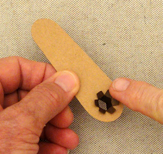
U-W handle rivet/screw accent shapes:
U base show-thru contrast to screw head semi circles
V rivet rim (match to handle paper)
W screw head semi circles
2. Prepare the handle build up layers so they can
be allowed to dry while other assembly takes place.
Position and attach the interior handle layers in a stack,
taking care to align all outer cut edges as precisely
as possible.
Press the stack under a heavy, flat object such as
a book, or this fabric-covered repurposed flat weight,
to avoid warping or curling when liquid adhesive is used.
(This may take one hours.)
3. Identify the base boxing strips which include tiny
punch holes in the end tabs.
(NOTE that finger/thumb grab holes or push through tabs
have been added to the BASE panel and BACK DISC
in the final cut file.)
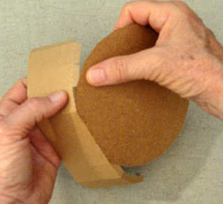
4. Prepare the boxing strips by bending back the segments
of each on perforation lines, also bend back along
perf lines of all side and end tabs.
5. Position the BASE panel bottom straight edge
along the center bottom, overlapping the flange to
the perforation line, adjust then glue in place.
6. Work up one side, bending to align the next segment
straight edge with the corresponding tab perforation
line, and gluing in place. Then . . .
. . . continue to complete
all segment edges and tabs on one side.
NOTE that the assembly can be placed face side down
on a flat surface to allow fingertip pressure to be
applied along all the tabs for firm attachment.
7. Repeat for the segments on the other half.
8. Position the upper boxing strip so that the straight
end overlaps the end tab/flange of the lower strip,
adjust and glue the seam.
9. Repeat for the opposite side seam.
10. Apply adhesive to all the tabs along the upper
boxing strip, then work quickly to align the center top
edge, then adjust and attach tabs along each side
until all are attached.
11. Repeat steps 5-10 for the box LID.
12. Position and attach the front whole disc over
the LID box assembly, centering for offset overlap
all around except at lower long segment.
13. Repeat for the back whole disc, taking care
to line up the thumb/finger holes with push through tabs.
14. Prepare the dimensional disc rim strip by adding
a little curl to it using a rod or dowel tool.
15. Bend the tiny tabs back so that they will be inward.
16. Form the strip into a ring, face side outward,
to overlap the straight end to the perf guide marks,
and glue the seam.
17. With tabs downward, apply glue to the backside
of tabs all around, then . . .
. . . slip the base disc into the ring and press into place
to fit snugly at the bend line between strip and tabs.
Place the assembly on flat surface to press fingertips
or tool - as shown in following photo - to assist the tabs
to attach (shown after the contrast accent shape
is positioned and attached in place).
18. If needed, the accent disc can be identified
as NOT being the base disc by the tiny notch cut out.
19. Position and attach the top accent cutouts disc
inside the rim ring and attach in the same manner.
20. Position and attach the front disc and rim.
21. Position the dimensional disc assembly over
the front of the accent disc, align the center hexagon
openings as precisely as possible, then attach in place.
22. Prepare the post strips by bending back along
the vertical panel perforations and end tab,
and also bend forward the top and bottom tabs.
Prepare the knob strip in similar manner,
bending the top wedge tabs back and top hex cap back.
23. Form the strips into a tube to overlap the sidestraight edge over the opposite tab to perforation line
(knob strip shown here).
NOTE that this may be easier if working with a 5/16"
wood dowel as a 'form' to wrap post or knob strip around.
24. For knob, move the post tube to one end of dowel,
then bend the wedge tabs inward, and . . .
. . . cap down into place and glue all securely.
For other post strips, the end tabs remain simply bent.
25. If using wood dowel 'nubs' as knob or post insert
for reinforcement or strength, bend bottom tabs (knob)
back out of the way and mark with fine pencil or other
a line as cut off guide. Then cut the dowel segment
and sand rough ends as needed.
26. For the posts, move the inserted dowel cut end
to align at the tab perforations at one end, then
bend opposite end tabs out of the way to mark.
Then cut the dowel segments to marked size.
27. From the face side of top hand layer, insert
the knob tabs through the hex opening, then . . .
. . . bend back and glue in place on underside.28. Repeat for the bottom handle layer with
the designated and prepared post strip.
29. Insert the appropriate dowel nub into knob
tube fully and glue in place.
30. If preferred, cut and use the card stock slot-together
X reinforcements as shown, intersecting the two strips
at slots and pushing fully together so that top and
bottom edges align.
Insert X strut into the open end of knob or post
so that the 'X' arms fit into opposite pairs of bend angles.
Slide fully inside.
31. Position and attach the handle top layer onto
the top of the built-up assembly; clamp in place if
necessary to ensure complete attachment.
32. Repeat for the bottom face shape and post,
attaching to the bottom of the build up.
33. Insert and glue the dowel post nub or X struts.
34. Insert the post end tabs through the center hex opening
of the front disc assembly, then . . .
. . . on the underside, bend back the tabs and
glue in place.
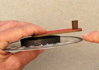
To aid the handle in "drying" in the appropriate
positioning, with parallel GAP between handle
underside and disc, consider propping it up with
something of the appropriate thickness.
35. Position and attach the front disc/handle assembly
onto the LID whole disc panel, and glue in place.
36. Assemble the handle pivot faux screw head
assembly by layering the ring on top of the base
with outer edges aligned, then position and attach
the screw head semi circles inside the ring.
37. Position and attach at center end of handle
as shown.
NOTE: the following few steps are for assembly
of the "optional" stand, which can be omitted if preferred.
38. Position and attach the top 2-3 oval panels for thickness
build up, taking care to align the hexagon opening cut edges
and outer edges as precisely as possible.
39. Position and attach the bottom interior panel
(with offset larger hex openings) to bottom of
build up panel.
40. Position and attach the accent shape on topof the stack, aligning hex opening edges carefully.
Press under a weight until dry.
41. Insert post end tabs through hex opening, then . . .
. . . bend tabs back within recess and glue in place.
Repeat for the other post.
42. Position and attach the whole bottom panel
to enclose the post ends inside.
43. Insert and glue dowel nubs or X struts inside posts.
44. Position post top tabs in "skinniest" formation, then . . .
. . . insert through the face side openings of
attachment panel, and . . .
. . . bend tabs outward and glue in place.
45. Position and attach the attachment panel
with stand along the bottom face of LID.
It is recommended to use a sturdy, quick-grab
adhesive such as Fabri-tack.
46. To close the box, insert the BASE into bottom
of LID (NOTE that this is a snug fit.).
Here is the completed reel box.
For extra authenticity, consider wrapping 14-16 yards
of twine around the boxing strips of the closed box,
hiding and securing ends as neatly as possible on
bottom panel, and weaving around stand posts
as needed as wrapping fills in.
Open box to insert the companion designFishing Hat Easel Card inside.


this is awesome. thank you for the very clear instructions.
ReplyDelete