Build
dimensional uppercase letter B composed of
LID and BASE, each with an interior
opening form
that makes fitting the curved boxing sections along those
openings.
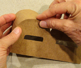
Then fit the lid and base snugly together.
Decorate the front of the
paired contrast ‘B’ overlay
with honeycomb accent layers.
Designed specifically
as the beginning letter of
the 3D letter boxes that spell out BLOOM.
Measures
approx. 6” tall x 3” wide x 1.75” deep assembled.
ASSEMBLY: 1. Identify and cut the shapes:
A 'B' Letter box main front panel
B-D LID boxing panels
E LID interior openings assembly insert
F & G LID interior openings boxing
H 'B' accent overlay and honeycomb overlay
(NOT SHOWN: optional wire attachment tab
for Bee 3D form attachment on lead boxing edge)
I 'B' Letter box BASE back panel with optional trap door
J-L BASE boxing strips
M LID interior openings assembly insert
N & O LID interior openings boxing
P optional support strut to stabilize 3D Bee wire
or tabs that help identify which strips ends join
and where the seams fall as they join to LID or BASE
main 'B' shapes.
Refer to this illustration of the B LID main shape (top)
and the B BASE main shape, and their associated
interior opening insert shapes to identify where
the boxing strips will be joined, according to symbols.
(NOTE: "T" in the insert shapes refers to "top".
3. Identify the boxing strip edges that will form
curves by locating the multiple wedge tabs.
Use a rod tool such as this rounded pencil shaft,or a comparable diameter wooden dowel, to add curl
to the segment of boxing strip, by drawing the strip
over the rod while applying finger (or thumb) pressure.
4. Visualize where the LID's boxing strips will be joined
4. Visualize where the LID's boxing strips will be joined
by forming, bending, shaping, then placing
across the top of the 'B', aligning the straight (uncurled)
segment across the corresponding portion of letter,
inserting the flange tab under the letter edge,
adjusting ends of strip segment with straight edge
of letter, and join in place.
Invert the assembly on a flat work surface to
apply fingertip pressure along the backside tab
to help secure the seam.
6. Position the curved portion of strip along the upper side
rounded edge of letter, adjust, taking care that
the end of strip aligns exactly at the end
of the curved edge (at the valley point)
and glue in place.
NOTE it will be helpful to invert the assembly in order
to apply fingertip pressure along the multiple tabs on
the underside to refine and secure the curve shape.
While the seam is still pliable/adjustable, work with
fingertips on the front side to adjust and correct
the curve seam.
7. Identify the next strip end by the tiny symbol
that corresponds to the first strip's end tab symbol.
Overlap the new strip's straight end edge across
end tab to perforation, adjust top to bottom to match
edges, then join seam.
8. Position the lower side curved segment along 'B'
edge, placing the end of multi-tab segment
at the transition angle where bottom straight letter
edge begins.
Adjust and align the strip edge with letter's edge,
then apply pressure to ensure secure and accurate joint.
9. Position, align and join the straight end section
in similar manner, taking care that end of strip
aligns at end of straight letter edge.
10. Locate and identify the final strip, overlap
and join end seam as previously done.
11. Apply adhesive to long straight edge and top end seam
tab, then position these along letter's corresponding
edges and join in place in one operation.
13. Prepare the interior opening TOP boxing strip
by bending forward at the cross perforations,
and bending back edge tabs.
NOTE that the upper opening boxing strip can be
identified with the 'T' symbol cut into the tab.
Use a rod tool to add tight forward curl at the multi
tab edges of strip, forming the strip by wrapping
around the tool and applying pressure by rolling.
NOTE: protect the narrow multiple tabs from tearing
by keeping them straight until the curling is completed,
then bending back into prepared position.
14. Form the interior strip into a rounded-ends
rectangular oval with face side inward, overlap
the end tab on the outward side and join the seam.
NOTE it may be helpful to insert a rod tool inside
the tube and under the seam being joined to provide
a "press-against" surface.
It may also be possible to press the tube into
a flattened position to apply fingertip pressure
along the seam to join.
15. With tabs bent outward as shown here,
position the upper opening tube behind the guide form
corresponding opening (NOTE the arrow symbol
near top indicates 'UP' orientation) . . .
. . . to align tab edge perforations along
cut edges of opening.
Adjust edges to be as precisely aligned as possible,
then glue the edge seams.
16. Repeat the process to form the lower opening tube,
position and attach at lower opening edges of guide.
17. Position the guide shape on the inside of the LID
box, with guide openings aligned precisely behind
the main letter's corresponding interior openings . . .
. . . and glue in place, inverting onto a flat work
surface to apply fingertip pressure all around
opening tabs to attach guide securely inside LID.
18. Repeat the process to assemble the BASE
(reversed) letter 'B'. This image shows the front
BASE boxing strip being added to the lead straight
edge of the optional 'B' with trapdoor.
When needed to provide interior access
to allow for Bee 3D form wire insertion, the door
can be detached by simply tearing away where
a top "bridge" holds it in place.
NOTE: When building the BASE shape that will have
the support strut inserted to hold Bee wire, it will be
helpful to trim away excess BASE guide straight edge
so that only approx. 1/4" margin remains.
(This avoids build up that may affect how
BASE height matches up with LID height
when strut is inserted.)
Narrowed trimmed edge can still be positioned
and glued into place at 'B' BASE interior openings.
19. Position, align, adjust and attach BASE interior
openings assembly in place inside BASE main assembly.
20. If your project will use the interior (in BASE) strut
reinforcement, prepare it by bending the cross perforations
into zigzag shape, then tend side tabs back.
21. Use the end of the Bee's wire to poke through
the marked insertion points (preferable NOT to
create holes any larger than the actual wire fits through.
22. Position the strut down the straight "channel"
in the BASE, placing the top lead end into the corner
angle, then arranging so that the bend angles
touch or come close to touching the front wall
AND the interior opening walls. This will help the holes
align down the center, and line up under the top boxing
strip hole.
23. Make sure the trap door is open to assist
directing the Bee wire when inserted after letter box
is finished being assembled.
24. Fit the LID over the BASE, directing the LID interior
openings walls to the inside of the BASE interior
openings walls.
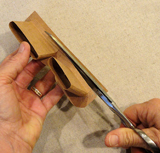
NOTE: this can be a tricky and time-consuming
portion of the assembly. If the fitting and closing
becomes to frustrating and difficult, one option is
use hand-scissors to cut down through the BASE
interior opening BOXING wall to perf line, allowing
the BASE interior openings to be opened more fully
to allow LID within.
Also, use a thin blade tool such as this spatula to
reach between the two forms to guide and adjust
as they fit together.
25. Once the LID and BASE are together fully,
flex the outer walls to apply quick-dry glue between
then immediately . . .
. . . cup the form between fingers and palms to
press inward to create a tightly fit, unified shape.
Repeat for the interior openings to attach those
walls to each other in similar manner (use tools
if necessary).
26. Position, align edges that match, and join
the honeycomb overlay on front of B main panel.
27. To attach the Bee stem through top, open
trap door and insert through outer top hole,
and feed through strut poked-holes.
When fully into place in desired extension
position, apply hot melt glue beads around
wire positions at strut holes, and hold
in place until cooled and wire is secured.
28. If side mount is preferred, determine Bee's wire
length and shaping, then position end on the side front
boxing panel and glue in place with hot melt glue,
then immediately position and assist attachment
with the attachment tab.
Here is the B Letter Box project with the BEE 3D
in place as side mount.


No comments:
Post a Comment