
Designed for Twelve Days of Christmas gifting,
this tray container is decorative
and functional,
put together with dozens of structure and accent shapes.
(Main structures require approx. seven 12x12 sheets
of card stock paper.)

Dimensional dove
head and torso emerge from oval tray ends,
with fancy wings layered for
thickness bending to hug side walls.
Divider has handle, providing tray more
weight and strength.
Multi-shape folk art decorations featured on dove,
walls
and divider overlays, as stencil cutout
(for two-colors only project) or filled
in to simulate painted details.
Scalloped base is layered for thickness and weight.
Sturdy design allows for storage and repeated display.
Measures
approx. 10.25” long x 5.75” wide x
4.75” tall when fully assembled.
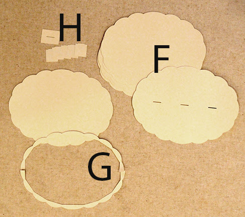
ASSEMBLY: 1. Identify and cut the tray container shapes:
A main side walls (2) B tray base
C decorative rim bases (2) overlays (2) with detail dots
D side wall accents and representative details (2 full sets)
(NOTE: the accent panels are significantly covered by
the wings, and some of the details will be hidden;
study the opening thumbnail to determine if you
wish to eliminate any of the details that won't show)
E rim "squaring" tool (4 to layer)

F scalloped base to layer for thickness, weight (5)
G (split) rim edge (4) with optional no-slots whole base
H slot sample (1) with base thickness testing nib tabs (5)

3. Identify and cut the dove and wings shapes:
I left & right dove head side panels
J left & right dove head accent panels
with representative accent details
K head boxing strip L boxing strip front, back overlays
M wing bases left & right (2 each)
N wing large layers left & right (2 each)
O wing middle layers left & right (2 each)
P wing top layer "base" left & right (1 each)
Q wing top overlay accent left & right (1 each)
with representative accents left & right (1 set each)

4. Identify and cut the center divider panel shapes:
(NOTE: during engineering pre-build, it was
anticipated that the divider could only fit inside
constructed oval walls unit if divided and reassembled
inside the vessel compartment; actual building
showed the panels could remain whole.
Layout shapes R-T are shown in this image divided;
in the final file they are "whole".
Some assembly images also show them divided.
In addition, the center decorative panel is shown with
a base offset panel which was eliminated.)
R divider wall center layers with bottom NIB tabs (4*)
(*as determined in Step 5 with slot and nib testing)
S divider wall side layers (2 for front; 2 for back)
T divider wall outer layers with side tabs (2)
U accent walls (2) with
representative accent details (2 sets)
V divider handle base overlay with top overlay (2 each)

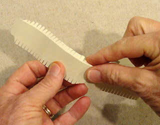
5. Before setting up and cutting divider wall shapes
(if possible), cut the slot test rectangle and the 4-5
test nib shapes.
Stack 4 of the test nib shapes from the cardstock
you have selected, then see if the
bottom nibs (shown at top of shape here) . . .


. . . will fit into the slot - snugly but not too tight
since the actual project will be glued together when
inserted. If 4 layers are NOT sufficiently snug,
add the 5th shape and re-try. Use the determined
number of fitting layers to cut that quantity of
divider CENTER shapes.

6. (Please imagine the shapes in this image as
connected and whole)
Layer and glue together, one by one, the divider center
walls with nib tabs shapes, taking extreme care
(here and whenever shapes are layered and glued)
that ALL cut edges are aligned as precisely
as possible.

Immediately (even while applying glue for next layer)
press the glued-up assembly on a flat work surface and
under a heavy, flat weight such as this heavy book -
with added weights of some kind on top if possible -
until thoroughly dried, up to several hours or
over night. This pressing will help reduce or eliminate
warping and curling of the stacked and glued shapes.

The pressing must be done for ALL layered shapes in
this project, but particularly the multi-shape layers such as
right angle tool, div. wall units, divider handles, box divided rims,
scalloped base and rims, dove wing units and assembly, etc..
It is recommended to review this complete tutorial to determine
those multi-layer shapes that need this pre-assembly layering,
gluing and pressing to complete these steps before beginning
the main assembly steps, to avoid excessing waiting time.
7. Layer and glue together the base shapes, taking special
care the slot opening edges are fully aligned and "open",
as well as outer cut edges.
(Take this same care throughout layering and glue-up.)

then position and attach on each half of the base
shape stack, with the halfway cut edges abutting snugly.

 10. Inset and glue in place the accent

9. Position the left & right head overlay onto
corresponding head base, offset along curved edges,
and edge aligned at the straight edges,
and glue in place.

details, including the "comma" overlay
on the main center swirl.
 11. Prepare to join the head shapes to the head

boxing strip by using a rod tool such as this wooden dowel
to add curl to the strip to imitate . . .
 . . . the curved edges shape of the head, that is,

UPWARD curl to the portion of top half nearest beak
tip perforation (shown above), then DOWNWARD curl
at the lower portion. NOTE that the positioning guide marks
will help to understand the shaping direction and transitions.
 Also add corresponding curl shaping to the lower front

portion of the boxing strip.
This image shows how the shaped boxing strip
is bent at the beak position, then the upper and
front edges echo the head base shape curved edges.
 Also bend back the tabs (add curl FIRST,

then bend tabs) while paying particular care . . .
 . . . to the narrowing of tabs near the beak bend.

Pinch the edge all along tab bends to establish
a crisp, consistent edge.
 12. Apply adhesive to the front boxing tabs portion.

Align the left head base shape assembly with
the beak angle at the boxing strip perforation,
and attach the first .75" at the beak, forming
the boxing edge and tabs to match closely
at the edge.
 Align the bottom .75" of base edge and boxing

and attach in place there, then . . .
 . . . adjust, push, form the boxing between the ends

so that it fits and shapes, then press to attach tabs
to backside of head base.
 When the boxing is firmly attached sufficiently,

flip the assembly face down on flat surface
to apply fingertip pressure all along the tabs
to assure accurate shaping and secure joining.
 13. Repeat the process for the top of the head

edge and boxing segment. Allow the glued tabs
to dry.
 14. Position the opposite head base assembly

over the other side of boxing strips, positioning
front edge, then top of head in sequence . . .

. . . reaching fingertips inside to assist positioning
and apply pressure.

and top, then . . .
 . . . position and attach each with narrow offset

at top, side and bottom edges in the corresponding
head boxing segment.


 For the top layer, the cut out wing is layered onto

16. Prepare the four wing layered components
by layering and gluing up the two layers of each.

As each component is glued together, bend back along
the perforation(s), just to "prime" it for the shape it
will need when finished.
(When the layers are pressed under flat weight,
the shape will need to be re-flattened.)

a whole wing shape.

Add the accent details to the "windows" of the top wing layer,
then bend along the perforation.

top wing over the second layer wing, with small offset
margin at edges, also taking care to align the perforations
of each component as precisely as possible,
then attach the two.
 18. Repeat for the third wing layer and the wing base,

with offset at edges, also align perforations.
 19. Position and attach the front assembly over

the back/base assembly. (Be sure to press under
a flat weight until thoroughly dry.)

20. Prepare the right angle wall rim alignment tool
by stacking and gluing up the 'L' shapes.

21. Prepare the wall shapes by bending BACK along
the wall segments vertical seams, wall bottom tabs,
rim edge perforations; bend FORWARD at "top"
(inside wall) tabs.

NOTE the miter alignment hash cuts at rim wedge
"tabs" - these are NOT actually tabs and
should not be bent.

22. Prepare the accent panel and header accents
then position and attach in place to the wall
panel segments, with offset. Add contrast shapes
into the cutouts.

NOTE the arrow head symbol in the center bottom
tab which indicates the center front or back segment.

23. Position the two sections so straight edge of one
overlaps opposite tab to perforation line, and join
first side seam. When first side seam is secure,
form the wall assembly into a ring to align and join
the second side seam.

24. NOTE that as the tray box is formed into oval,
the rims may start to fold over and intersect, with
a straight edge next to a triangle tab.
Eventually the straight edge should OVERLAP the tab
approximately to the hash cut mark.

Begin at the front or back center wall segment,
then carefully bend it back into the oval tray
interior . . .

. . . until the inward tab rests against and attaches
to the backside of the wall shape.
Before glue grabs . . .

. . . use the right angle alignment tool pressed
flush against the outer wall to help adjust the inner
attachment location to create a perpendicular rim.
With one arm of tool registering along wall face,
push the inner tab upward and level, to make
the rim surface fit along the cross edge, as shown.
Test check at each end of the segment rim face
to make an even rim, then press the tab to secure
in place. Allow the joint to get secure.

25. Work toward one side - right of center shown here -
to repeat the wrapping of inward walls, overlapping
the rim triangle tab of center segment, attaching
tab to inside wall face . . .

. . . checking for perpendicular rim and adjusting.

If the RIM OVERLAY arcs are NOT being attached
as decorations, the rims can be shaped by applying
a dab of glue to the triangle tabs prior to the wrapping
of inward walls. (Using rim overlays is more desirable
and secure.)

26. Continue along the first half in the same manner.
NOTE that the side/end segments (with slot),
the inward wrap will wait until later in assembly.

27. Continue in same manner toward the second
end of the first portion of wall, leaving end inner wall
free until later. Complete second half of oval
in similar fashion.

28. Assemble the divider layers by attaching
one straight lower edge stack onto one face of . . .

. . . the nibbed center stack with cut edges aligned
(except at nibs).

Position and attach the second straight cut stack
on the other side of nibbed center stack.

This image shows the center nib between the two
straight edge stacks.

29. Bend the end tabs forward on remaining (top) divider
layers, then . . .

. . . position and attach one on each face
of the stack, taking care with cut edge or tab perf bend
alignment. IMMEDIATELY press under heavy flat weights
until thoroughly dry - over night if possible.

30. Position and attach the accent panel onto
the divider stack, then . . .

. . . add and attach the detail accents.

31. Stack the plain handles with punch accent hole shapes
and glue the pairs together.

32. Position and attach the handle assembly onto
front and back of the divider unit.

33. Prepare the top layer rim, if desired, to define
the individual segments with distressing ink, by creating
a narrow inked margin at each of the dash cut markings.
One way to do this is to place a mask edge (post it note)
along the mark, connecting the outer corner and
corresponding inner angle, then adding a little ink. Then
Reverse the side of the mark that mask paper is
aligned along, and repeating the inking.
Another way to do this, as long as the BASE arch is
also used, is to simply fold along the dash cuts,
then while arch is folded, ink along the fold.

34. Position and attach the punched top layer arch
onto the base arch. Then . . .

. . . place and attach the circle detail accents.

35. Begin the final assembly by positioning the dove head
at one end of the tray to insert the tabs into slots of tray.

Push tabs in fully, then on the inside of end panel
bend the tabs outward and securely glue in place.

36. Bend the inner wall down into place
and attach tab . . .

. . . to the inner wall surface as with
other inner wall tabs.

37. Bend the dove head tab down and glue in place
to the inner wall.
(Repeat the head attachment for second head.)

38. Prepare the insert the divider by bending
the end tabs into perpendicular position as shown,
on both end.

Insert the divider through the bottom of the tray
into the tray interior. Then . . .

. . . insert the tray bottom "oval" in between the bottom tabs.
(Bend the bottom tabs up straight or back slightly.)

Apply glue to the inner surface of all the bottom tabs,
bend inward toward center, then . . .

. . . place the tray bottom-down on a flat work surface
then use fingertips to adjust the bottom to make sure
edge facets register exactly with wall edges,
as well as apply pressure all around. Circulate
fingertip pressure to make sure all tabs attach securely.
NOTE that the divider tray is loose inside the tray
and will need to be moved out of the way (side to side)
during this assembly step.

39. Apply adhesive along the center of base in a line
no wider than a generous 1/16", from tray end to end.
Also apply glue where the end tabs will attach to end wall.

Straighten the divider into its centered, vertical
position, so that the bottom nibs slot into the base slots,
bottom straight edge rests along base, and end tabs
attach vertically to end walls, below inner wall.
NOTE that the divider wall will also register into inner wall slot

On bottom, check to make sure that the nib tabs
are fitting into the slots properly, and are fully through.
Hold in place and apply pressure to attach divider to
tray floor, end tabs to end walls.

40. Bend the dove bottom tab into position and
attach in place.

41. Apply adhesive to the bottom of the tray assembly,
then fit the base assembly over it, fitting tray oval
in between the rim arc edges. Push the nib tabs through
the base slots, and apply pressure to secure together.
When attached sufficiently, invert the assembly
and apply pressure from inside to bottom of tray
to ensure strong connection. If available, place heavy
loose objects such as toy marbles or pie crust weights
to help attach base securely.

42. Position and attach each rim arch in place,
using fingertips to help adjust rim and arch
for most precise positioning and alignment possible.

43. Position and attach (with quick grab glue such as
Fabri-Tack liquid glue or hot melt glue) each wing
assembly in appropriate place on each end, next
to dove head, aligning bend perforation line along
the ridge of oval tray walls as shown.
NOTE that the wing top tip is positioned near
the upper corner of the wall segment next to side center
panel and head.

Here is the completed tray.

Add tied ribbon cluster as shown, if desired.

No comments:
Post a Comment